Flashing canoeboot on the Thinkpad R500
Table of Contents
Why?
While searching the internet i found the R500 guide saying the R500 was identical to the T500, guess we’re following the T500 guide guide. The fact there’s no dedicated guide for the R500, and the current one is outdated, was my motivation for writing this blog.
Updating the EC firmware
It’s recommended to upgrade the EC firmware before canoebooting the PC, while it’s unknown how to update the EC firmware once canoebooted. To update the EC firmware we have to update the BIOS, we can find the BIOS update here. After much trail and error I couldn’t get the OS Independent version working. Therefore i had to install Windows, i chose Windows XP (When flashing ISO to USB stick use MBR partition table). After installing the BIOS update utility software, we were faced with an error message: This process requires a charged battery to avoid an accidental power-off during an update. This was frustrating, the battery that came with the PC wouldn’t charge up to more than 5%. After searching online and trying multiple solution with no luck, I had no choice but to load up Binary Ninja and take a closer look at the binary. Once the binary was loaded we can quickly find the function causing the trouble: sub_402350. Taking a look at the decompiled code:
int32_t __fastcall sub_402350(CWnd* arg1)
{
  int32_t lpSystemPowerStatus = 0;
  int32_t var_8 = 0;
  int32_t var_4 = 0;
  fprintf(data_40db78, "%s", "AC adapter/Battery check....");
  GetSystemPowerStatus(&lpSystemPowerStatus);
  int16_t lpSystemPowerStatus_1 = (int16_t)lpSystemPowerStatus;

  if (!lpSystemPowerStatus_1 || lpSystemPowerStatus_1 == 0xff) {
    if (data_40db08) {
      fprintf(data_40db78, "%s\n", "Failed.");
      fprintf(data_40db78, "%s", "Error : This process requires AC…");
      CDialog::OnCancel(arg1);
      return 0;
    }

    CWnd::MessageBoxA(arg1, "This process requires power to a…", "Error", 0x10);
    fprintf(data_40db78, "%s\n", "Failed.");
    fprintf(data_40db78, "%s", "Error : This process requires AC…");
    return 0;
  }

  if (*(uint8_t*)((char*)lpSystemPowerStatus_1)[1] == 0x80 ||
      *(uint8_t*)((char*)lpSystemPowerStatus_1)[1] == 0xff) {
    if (data_40db08) {
      fprintf(data_40db78, "%s\n", "Failed.");
      fprintf(data_40db78, "%s", "Error : This process requires a …");
      CDialog::OnCancel(arg1);
      return 0;
    }

    CWnd::MessageBoxA(arg1, "This process requires a charged …", "Error", 0x10);
    fprintf(data_40db78, "%s\n", "Failed.");
    fprintf(data_40db78, "%s", "Error : This process requires a …");
    return 0;
  }

  lpSystemPowerStatus_1 = *(uint8_t*)((char*)lpSystemPowerStatus)[2];

  if (lpSystemPowerStatus_1 >= 0xa && lpSystemPowerStatus_1 != 0xff) {
    fprintf(data_40db78, "%s", "OK.\n\n");
    return 1;
  }

  if (!data_40db08) {
    CWnd::MessageBoxA(arg1, "Your battery needs to be charged…", "Error", 0x10);
    fprintf(data_40db78, "%s\n", "Failed.");
    fprintf(data_40db78, "%s", "Error : Your battery needs to be…");
    return 0;
  }

  fprintf(data_40db78, "%s\n", "Failed.");
  fprintf(data_40db78, "%s", "Error : Your battery needs to be…");
  CDialog::OnCancel(arg1);
  return 0;
}
It’s clear what we need to do, we must somehow make the function return 1, instead of 0, this can easily be done by replacing the function code with the following instructions:
mov eax, 1
ret
Finally it was working, this meant we could update the EC firmware (check out my patches here.)
Preparation
Before disassembling the Thinkpad and flashing the chip, we need to set up the programmer. The programmer of my choice is the Raspberry Pi Pico, it delivers 3.3V instead of 5V like the popular choice: CH341A. Overloading with power to the these delicate old chips can easily fry them.
Firstly, we’re going to download and flash firmware onto the Pi. I’m going to be using Pico Serprog. For the flashing part, press and hold down the BOOTSEL button located on the Raspberry Pi. Then while holding the button connect it to your PC, then release. You’ll now have access to it through your file manager of choice. Copy paste pico_serprog.uf2 (downloaded here). Now disconnect the Pi! Now we’ll download flashrom, sudo dnf install flashrom. As well as the BIOS for our Thinkpad. This can be found here, under the /20250107/roms/, here we see the file canoeboot-20250107_r500_4mb.tar.xz.
Disassemble
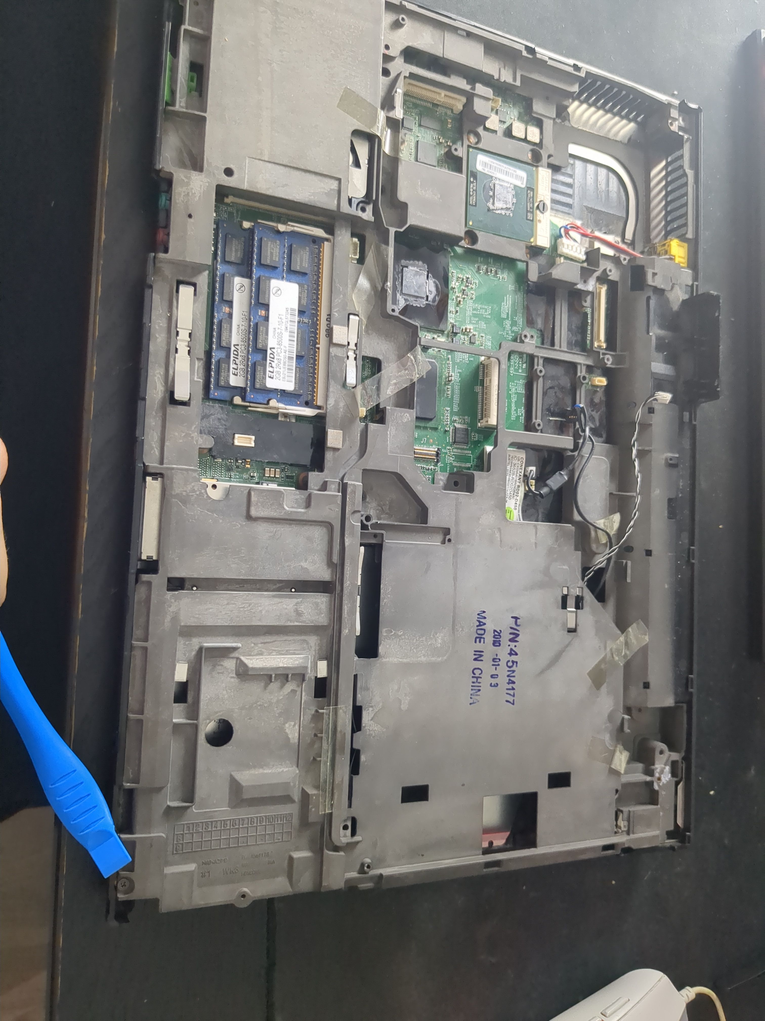
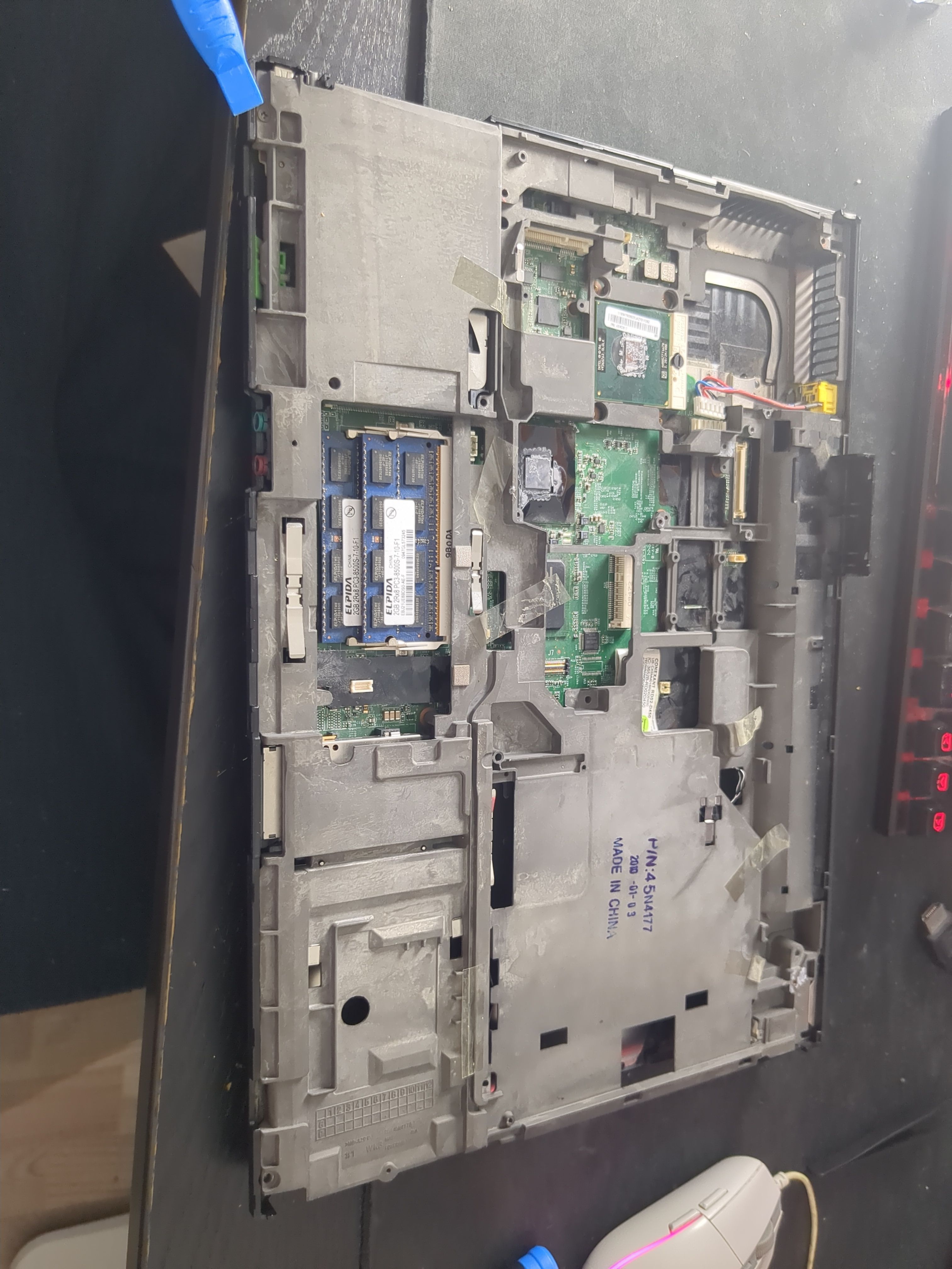
Now we’re all set to disassemble the Thinkpad. First we must disconnect the battery. Make sure to note down which screw goes where, I’m doing it like the illustrated pictures:
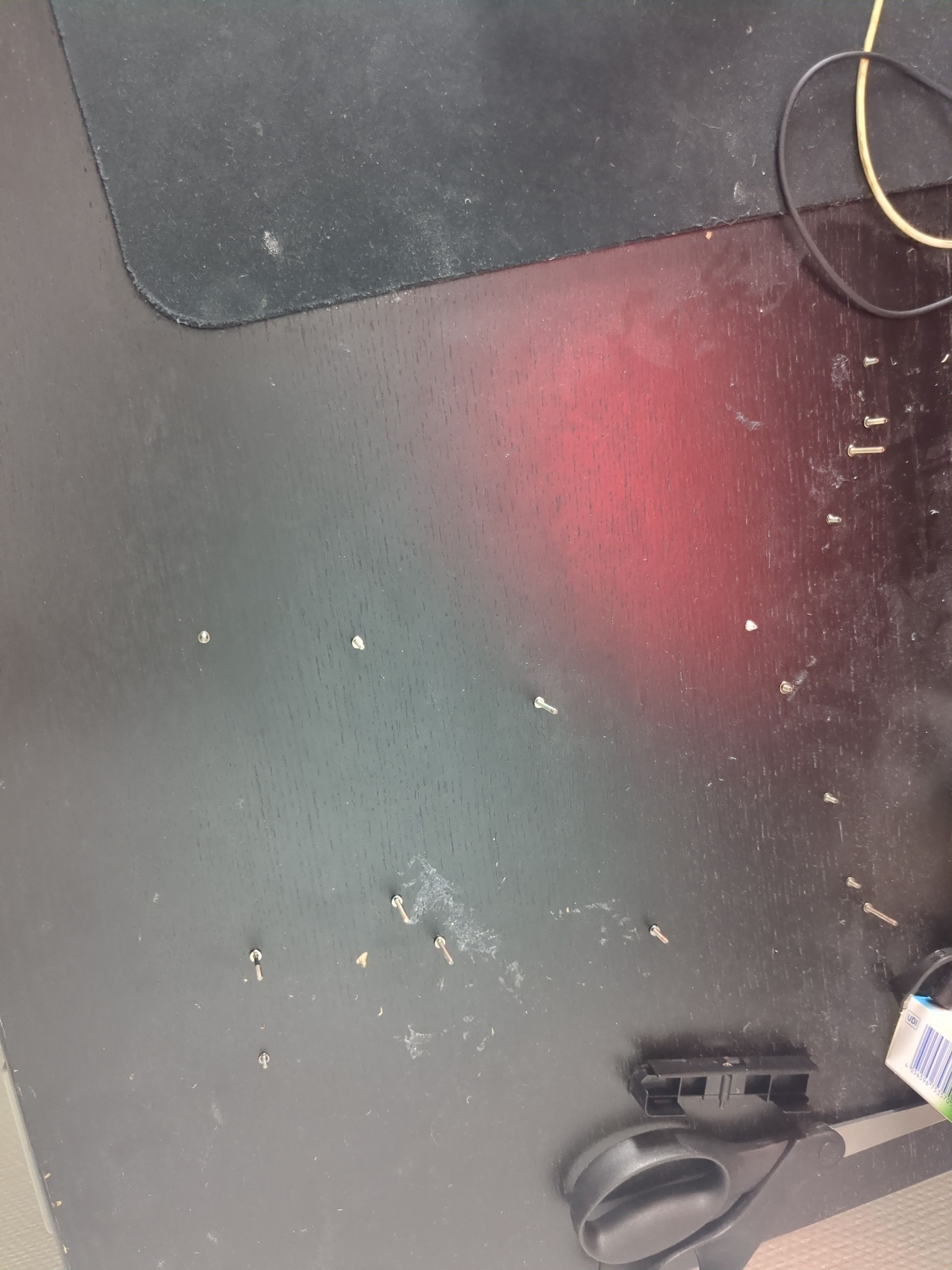
Now remove all visible screws using a Philips 1 screwdriver:
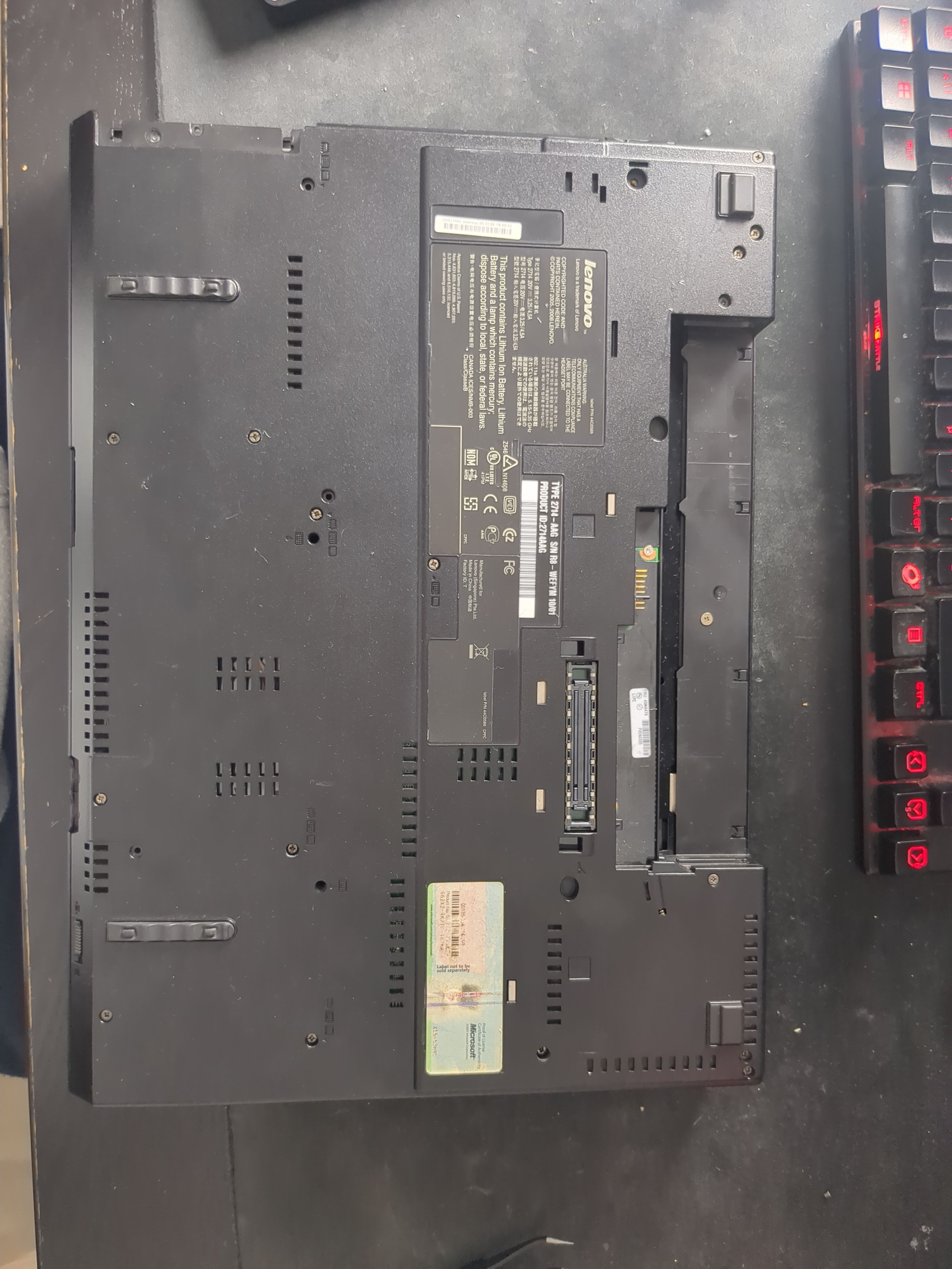
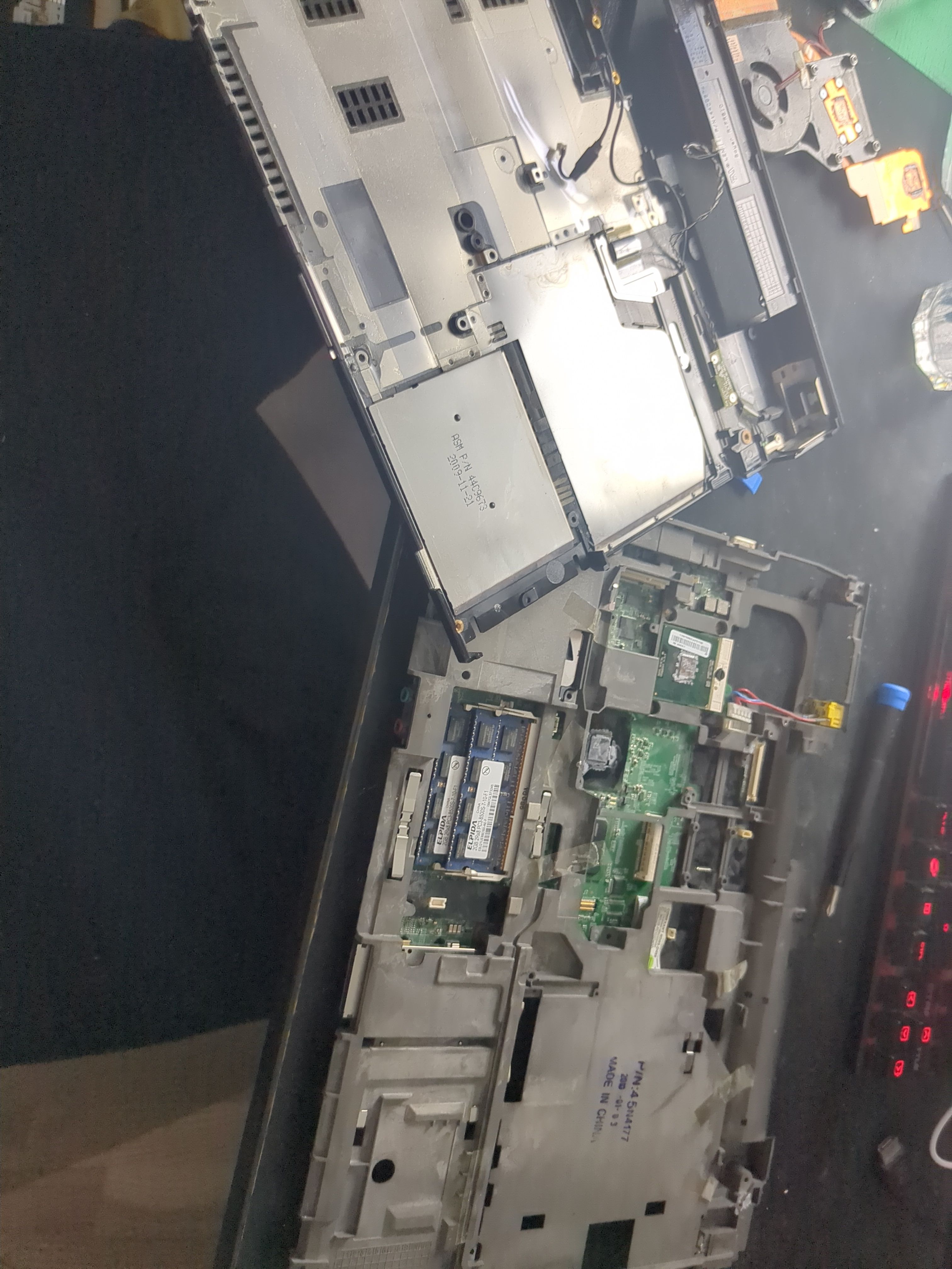
Remove the internal DVD drive:
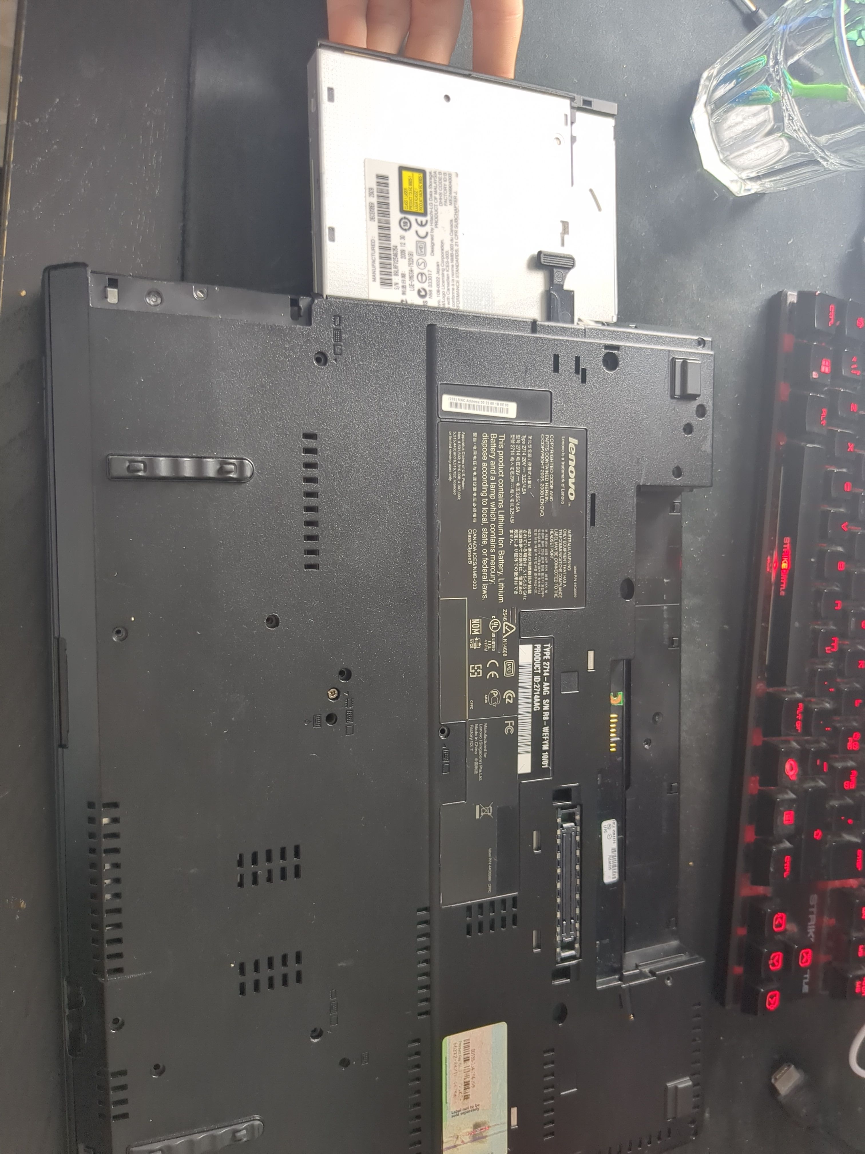
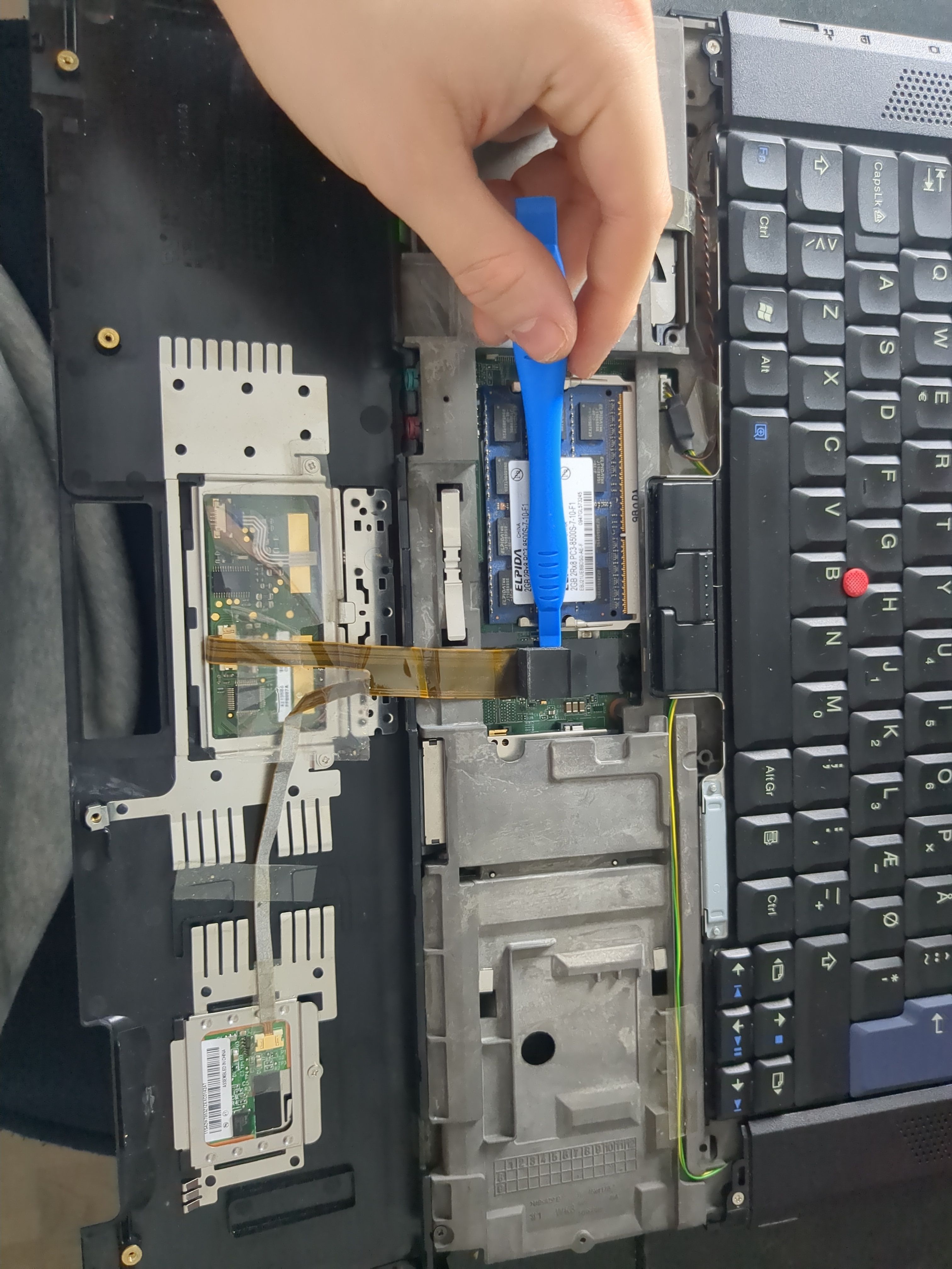
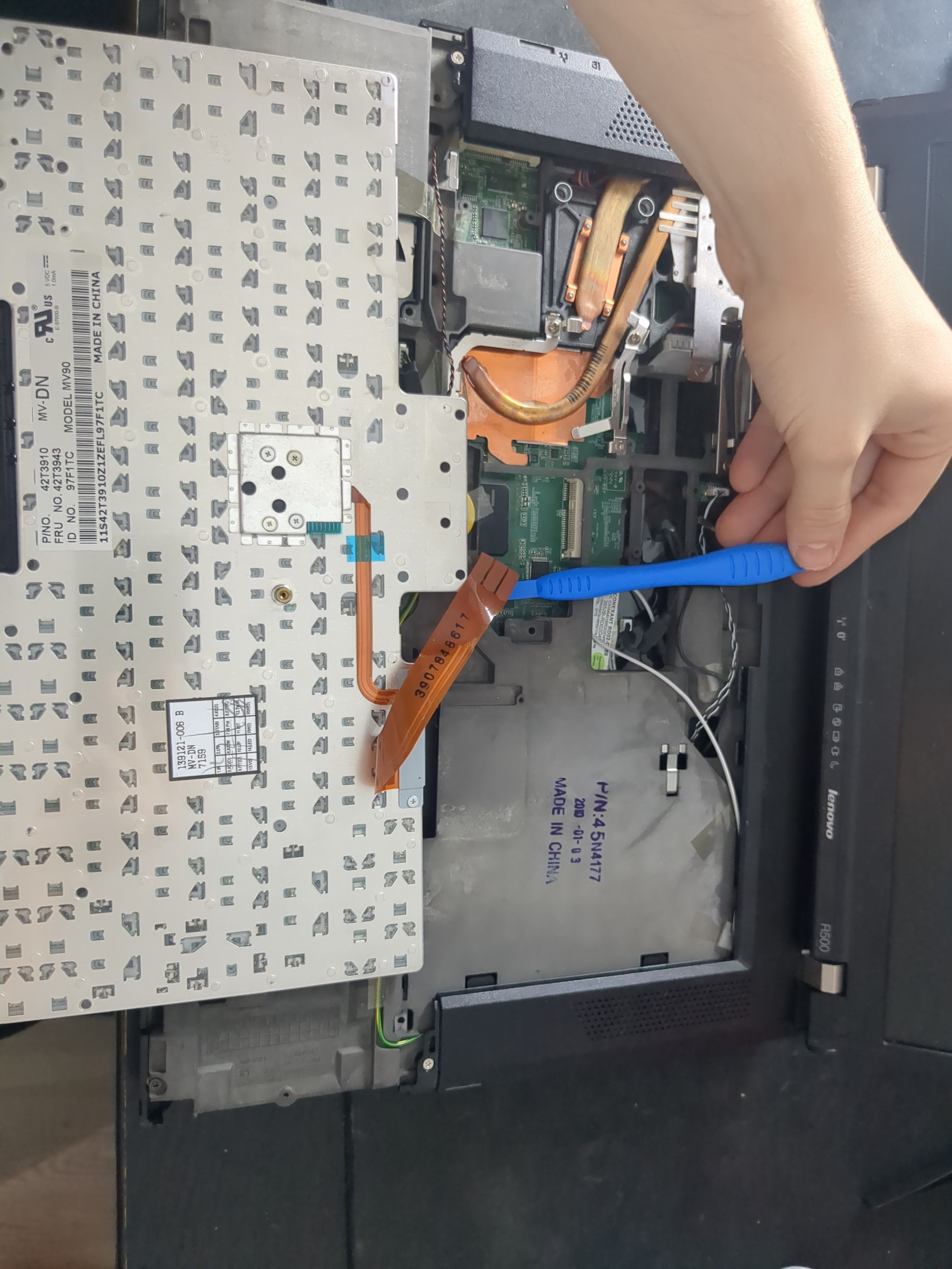
Remove and unplug the palm rest and the keyboard:
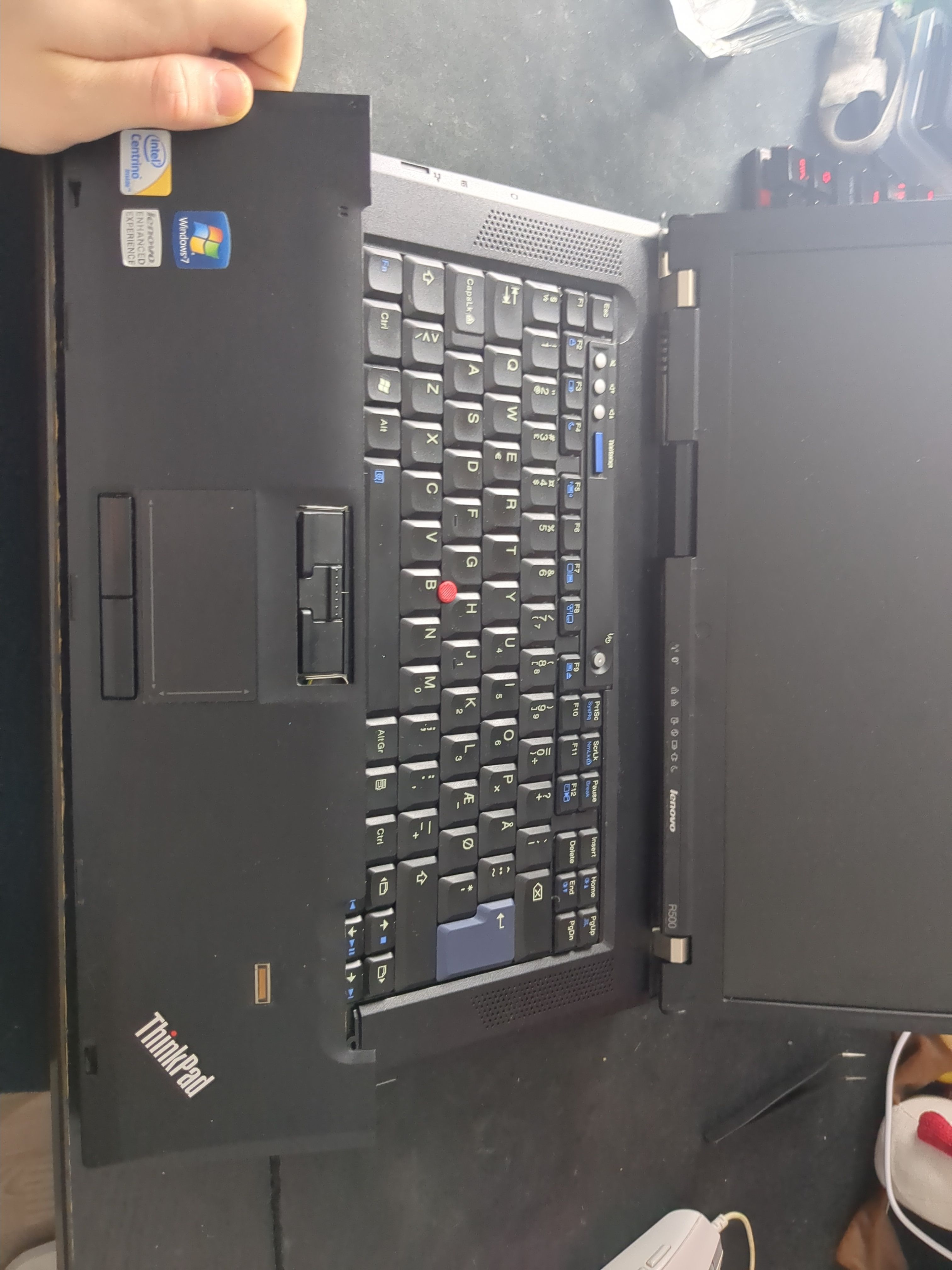
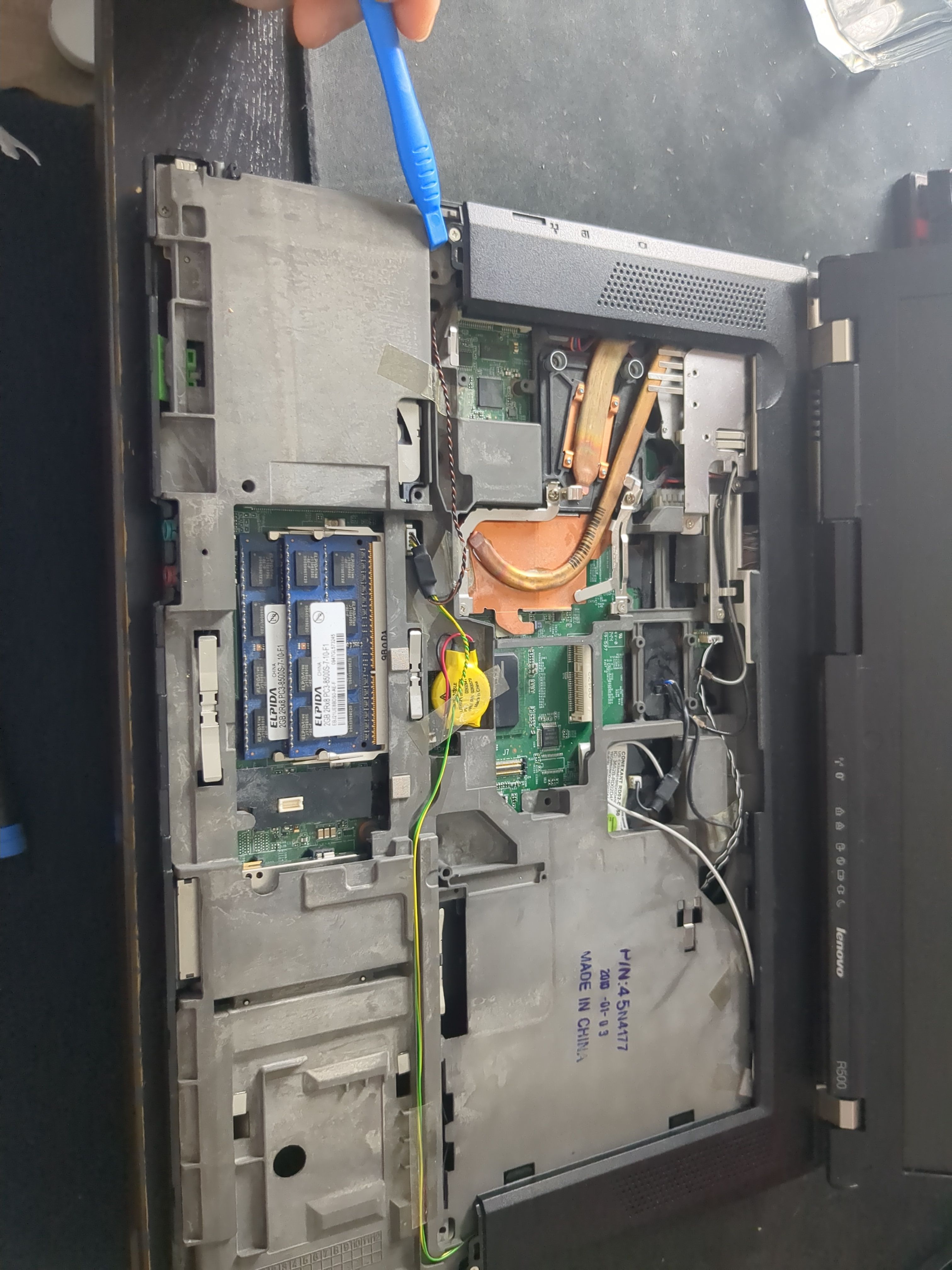
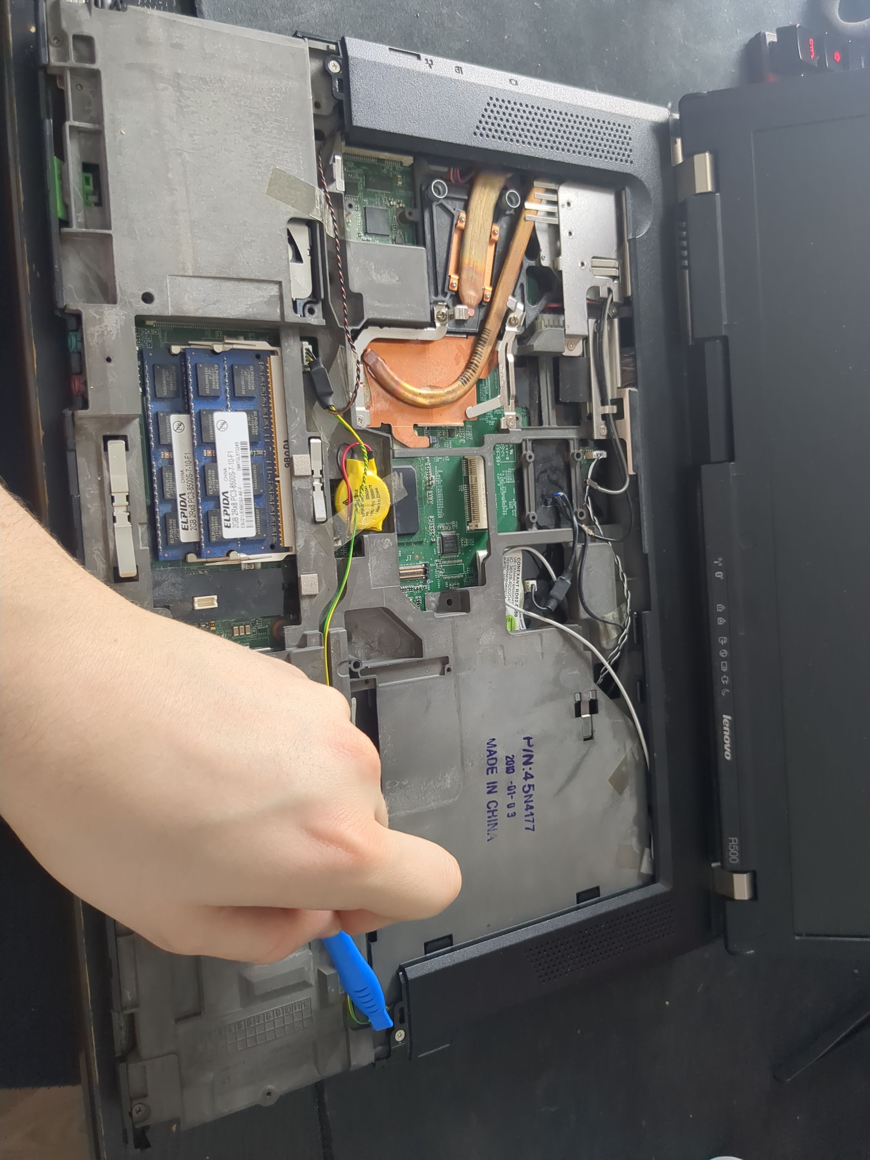
Remove the screws shown in the picture:
Disconnect the audio:
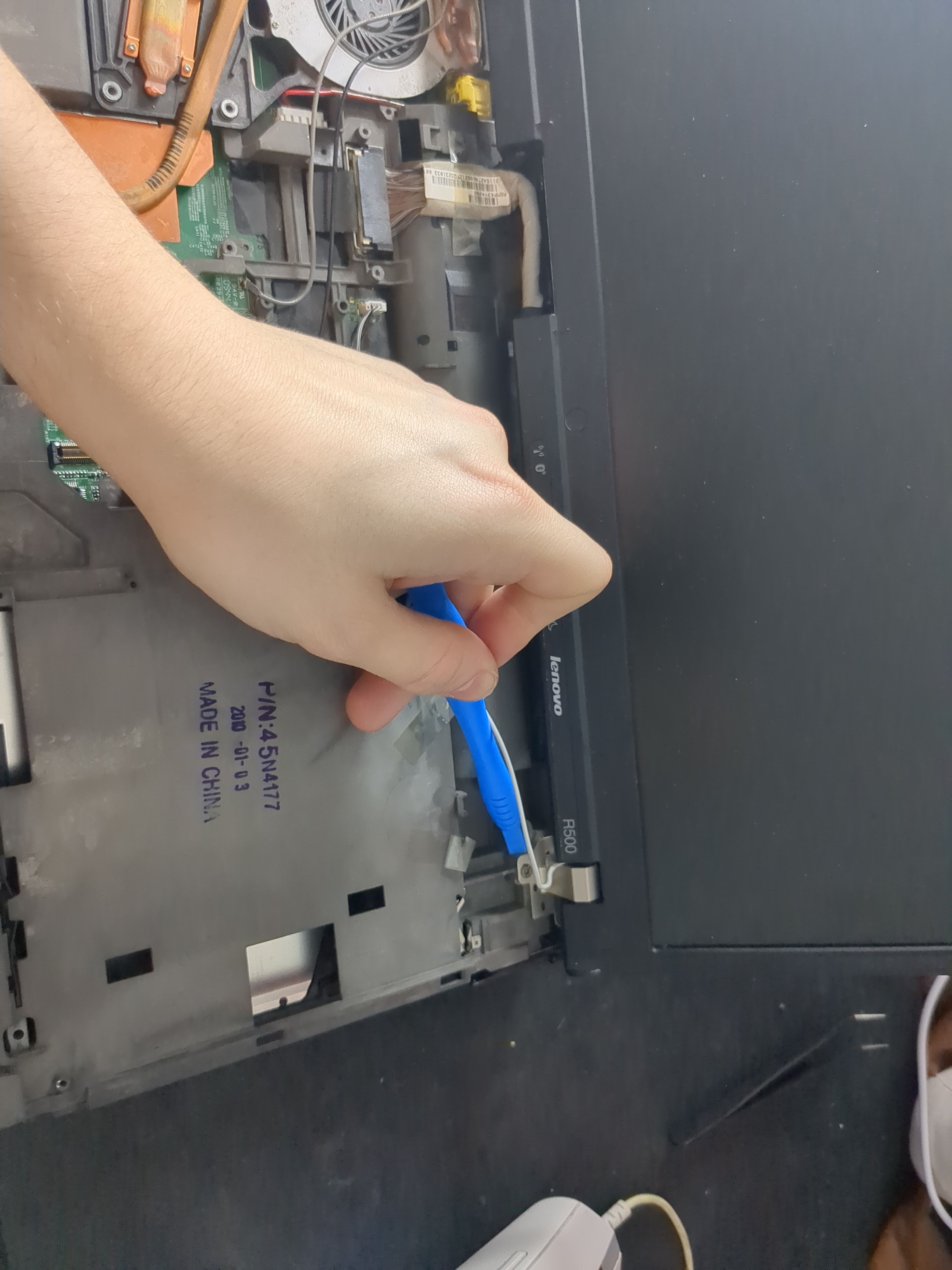
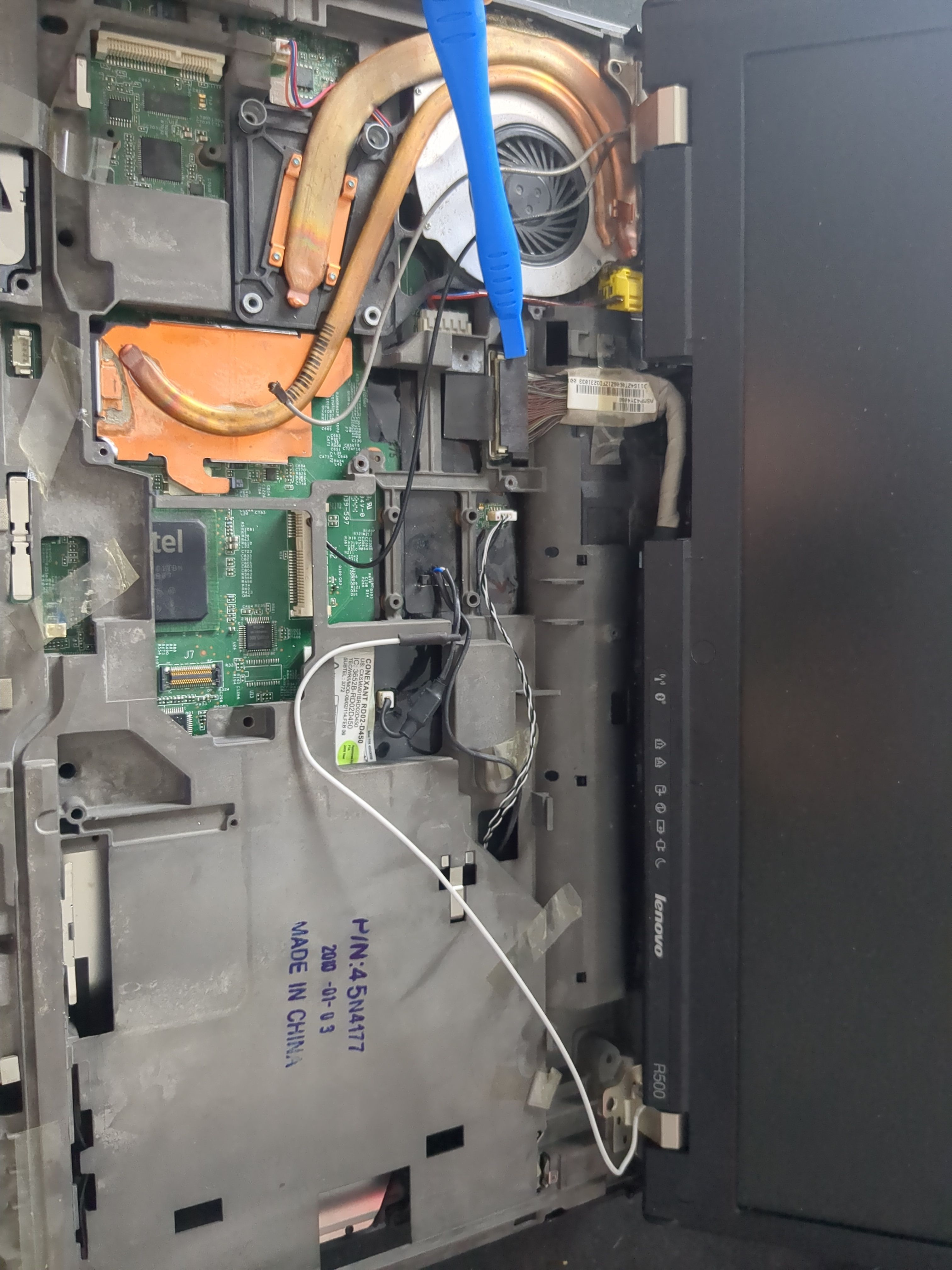
Remove the rear bezel:

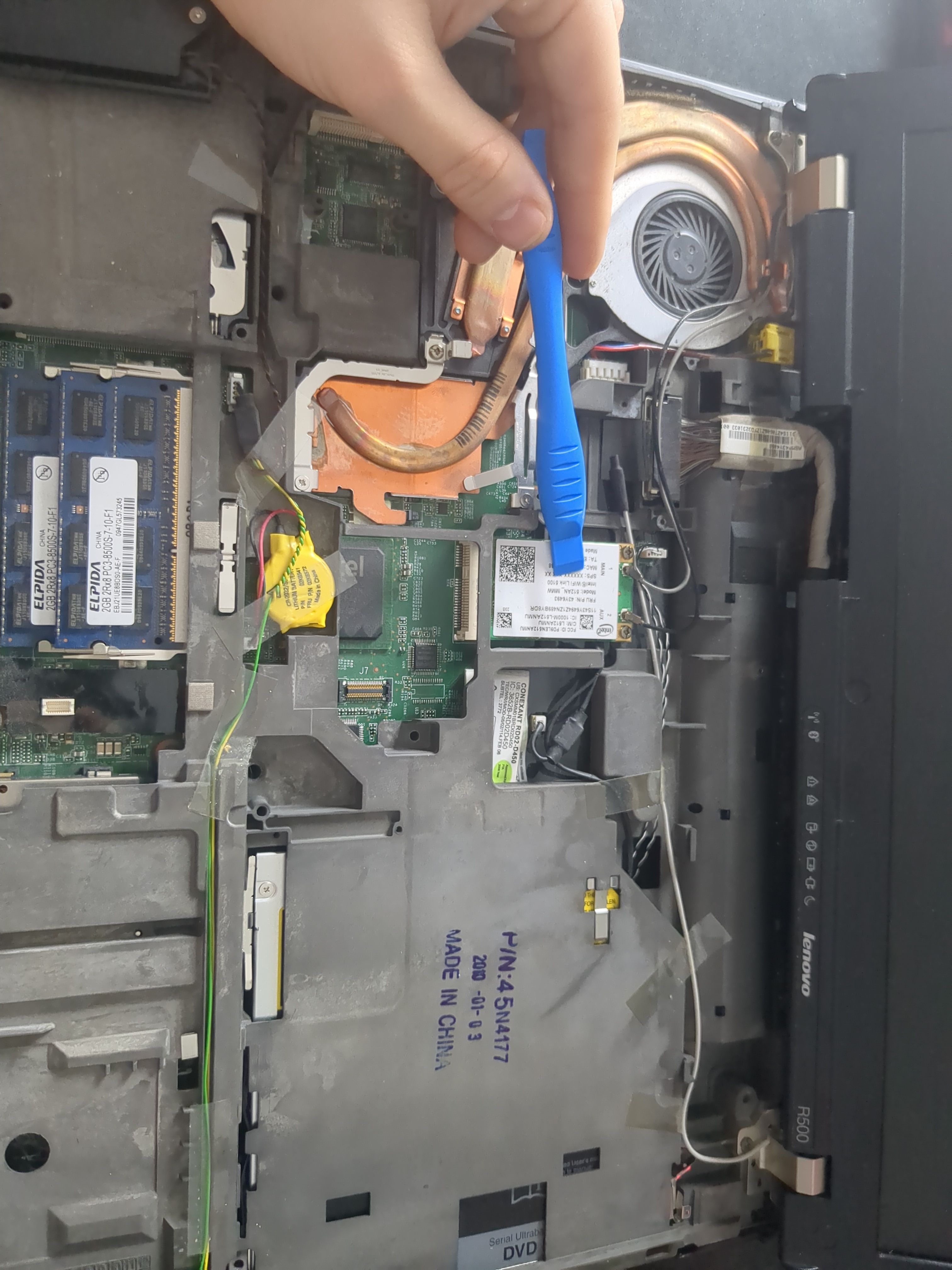
Remove the WiFi card:
Remove the display by removing the screws, and disconnecting the cable:

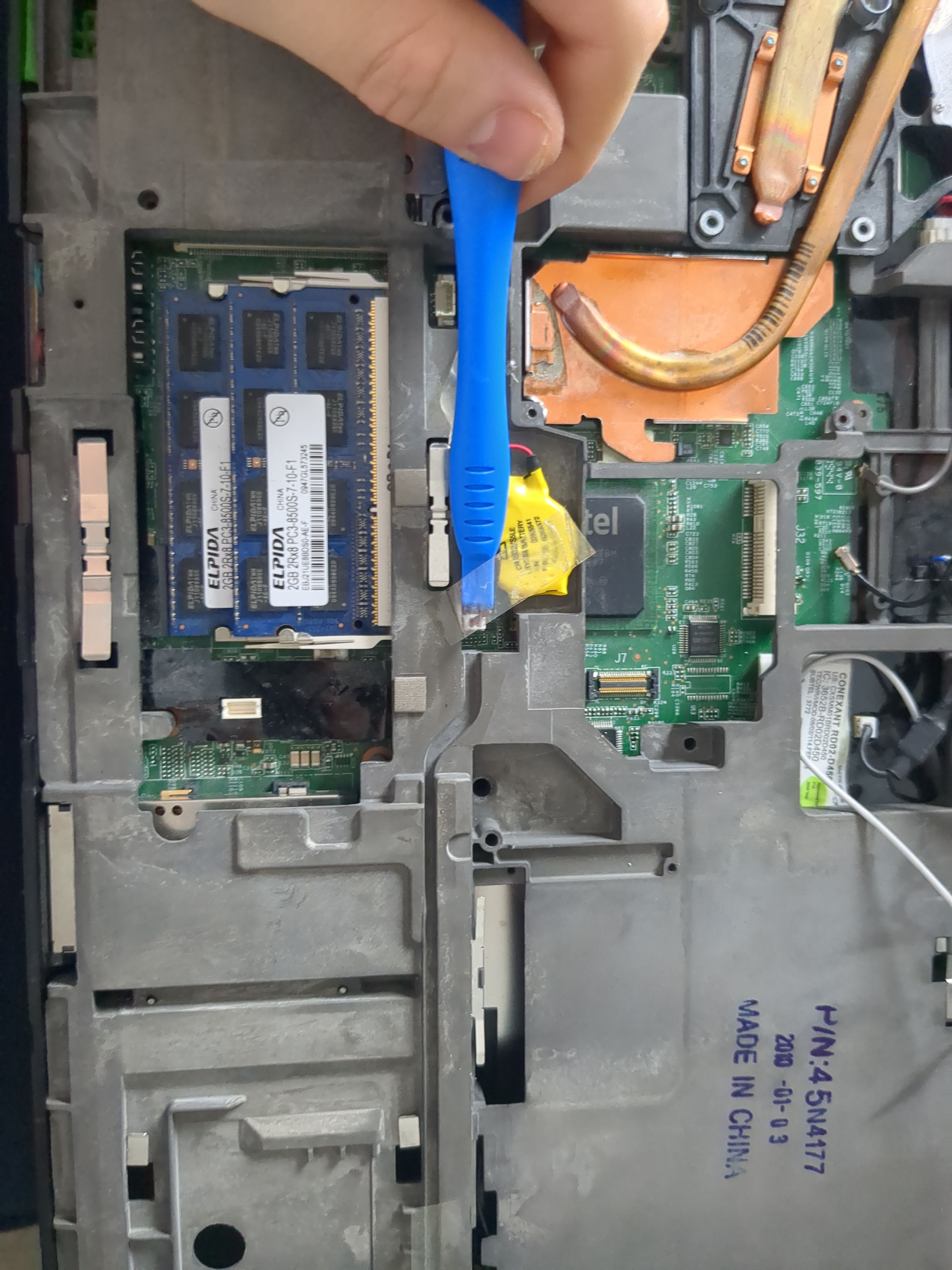
Remove the NVRAM battery:
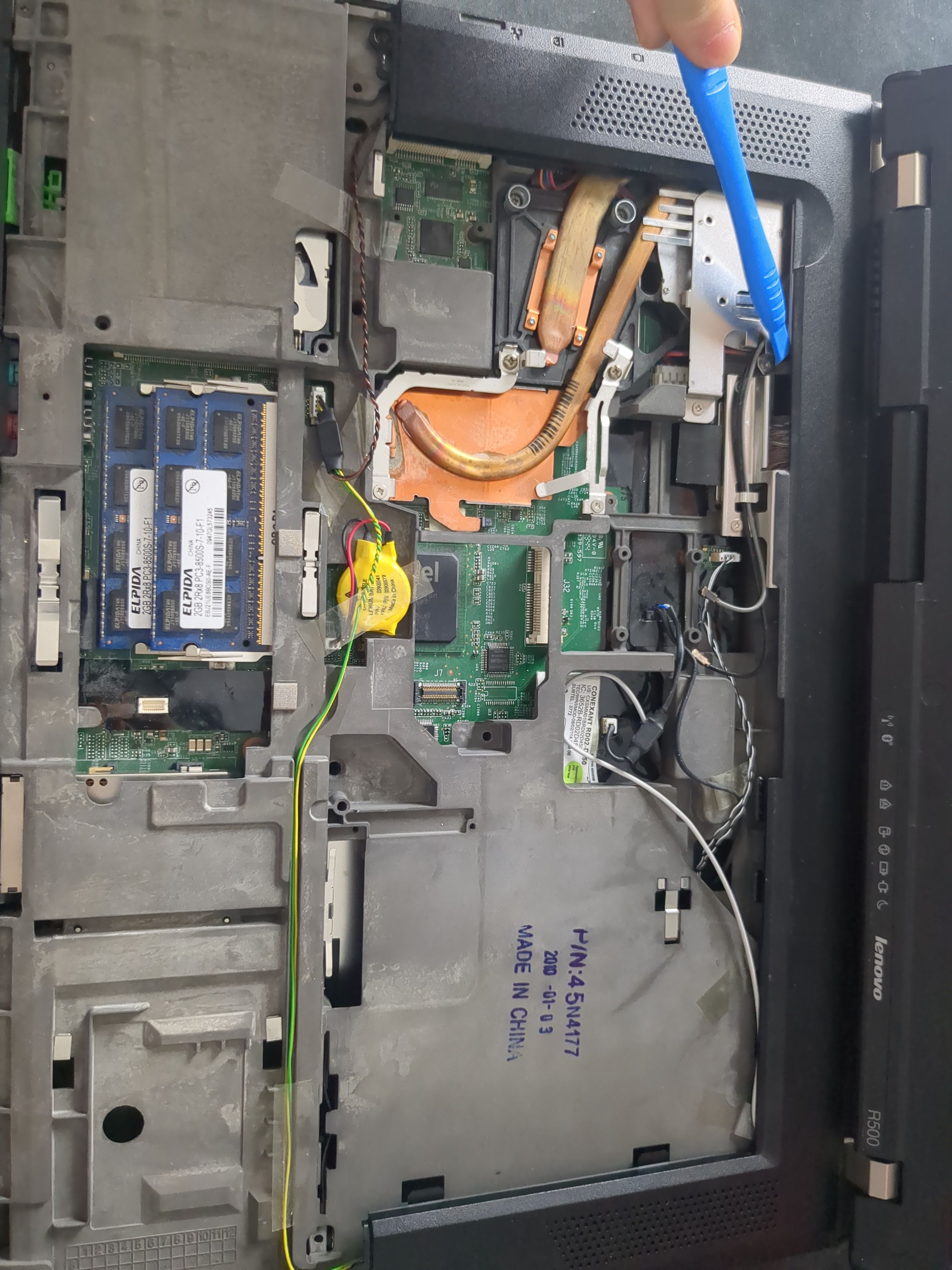
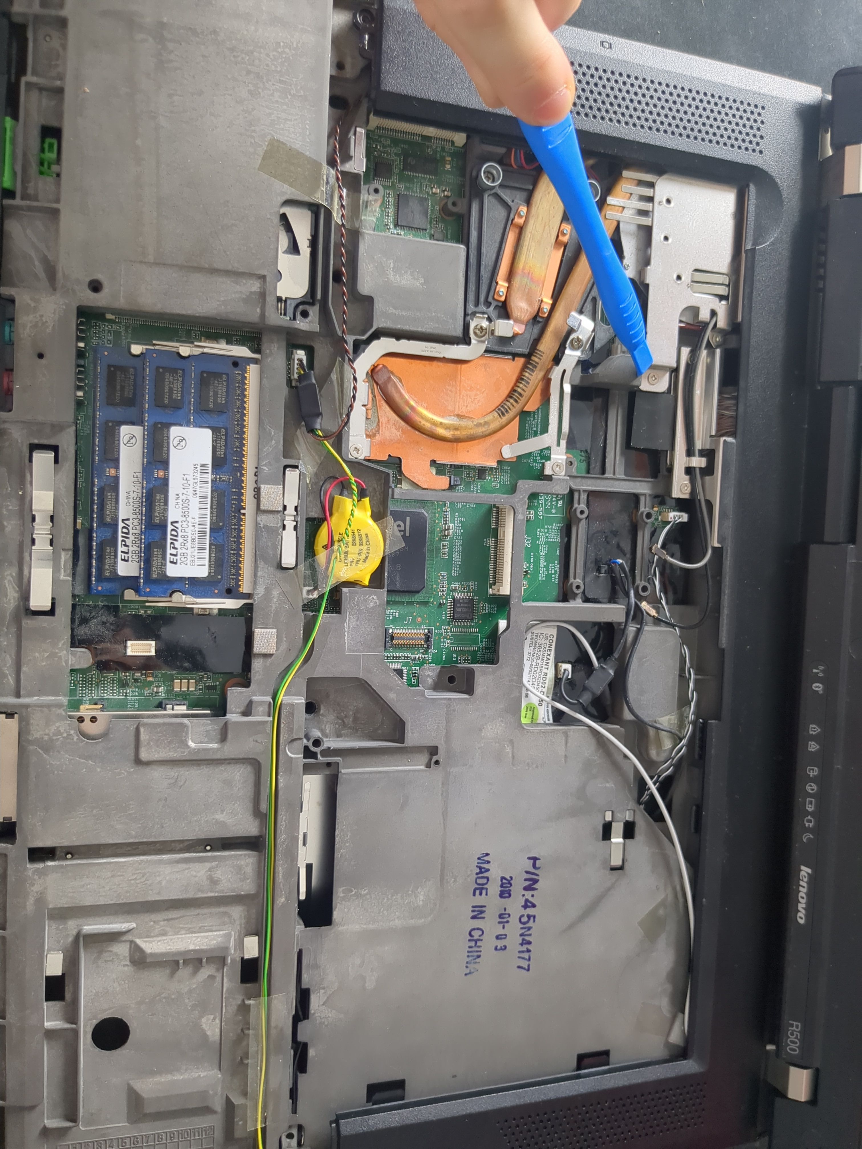
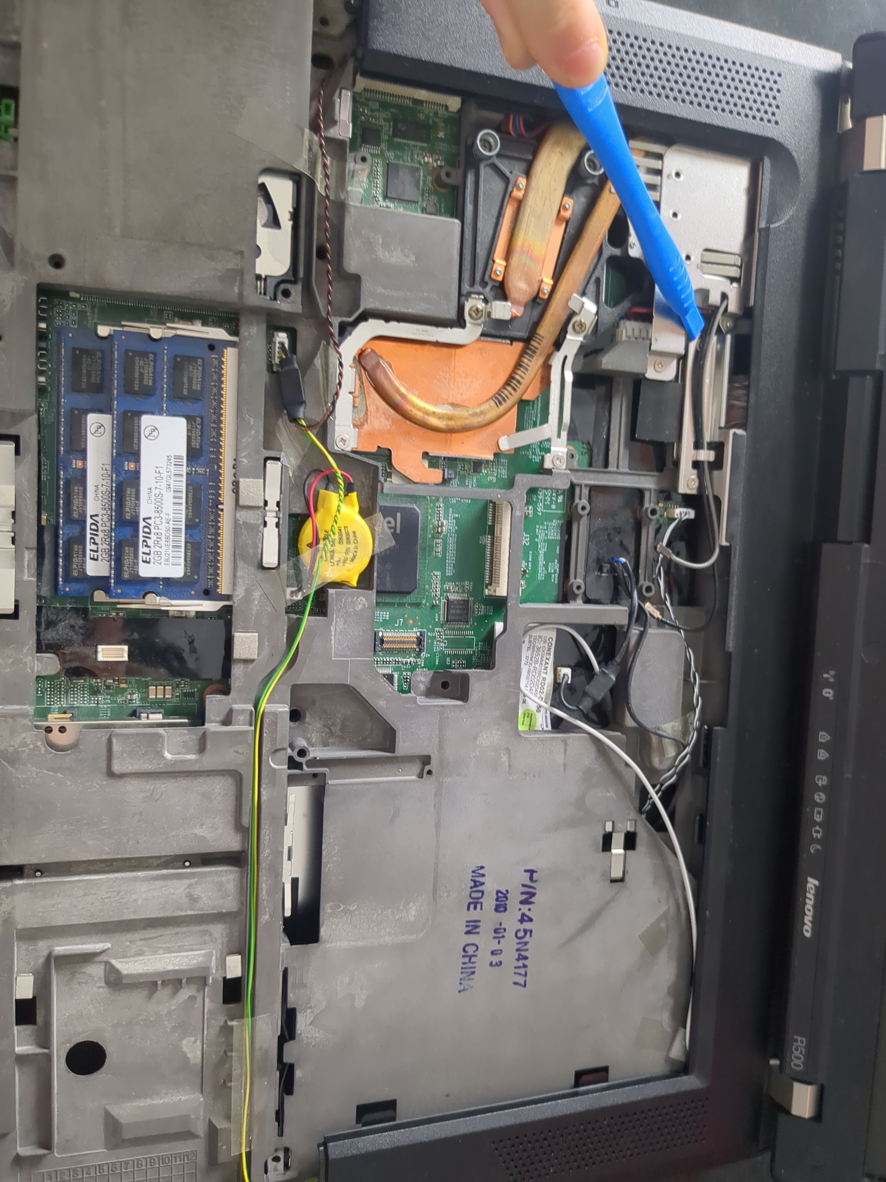
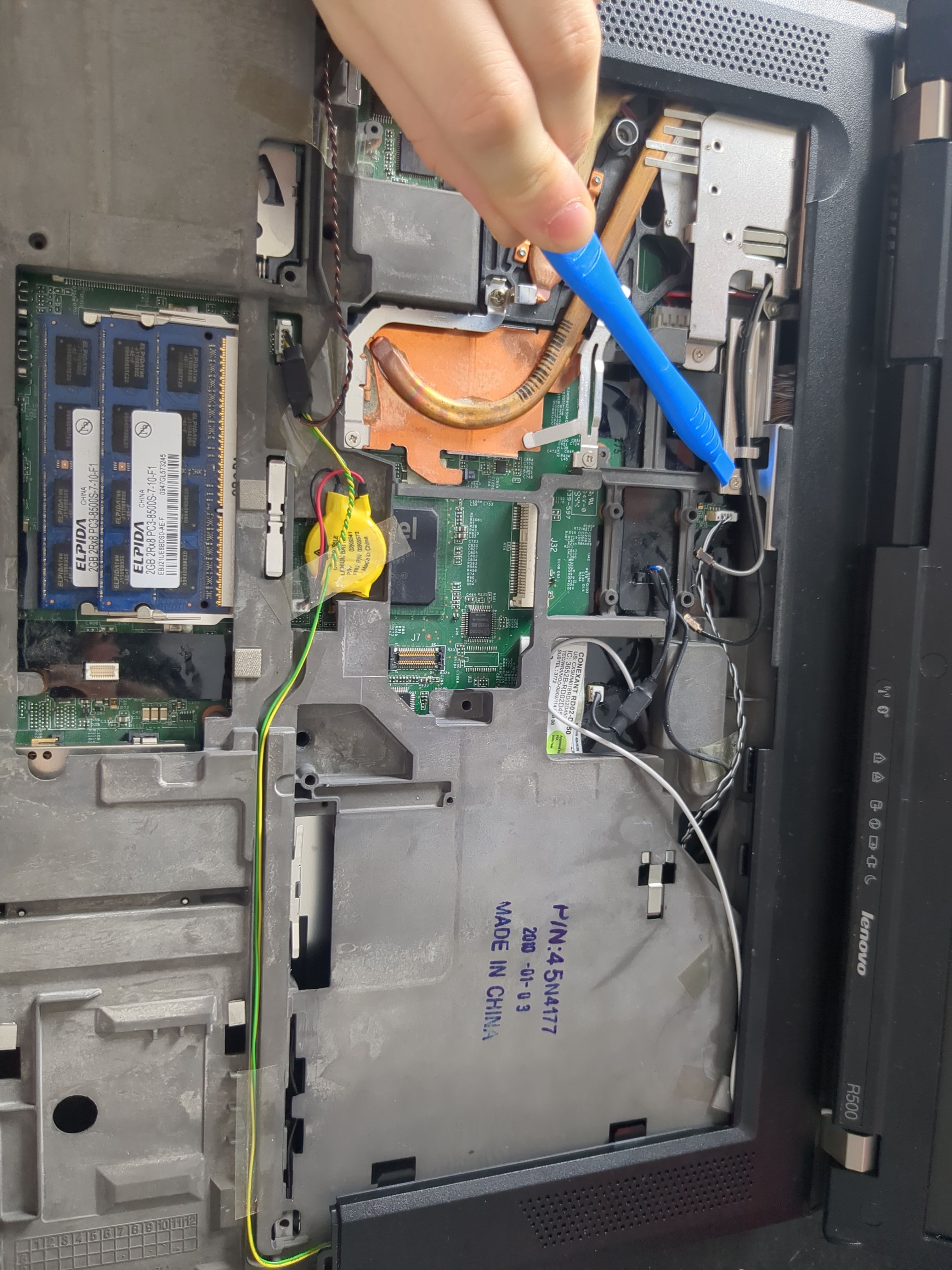
To remove the cooling system, remove following screws:
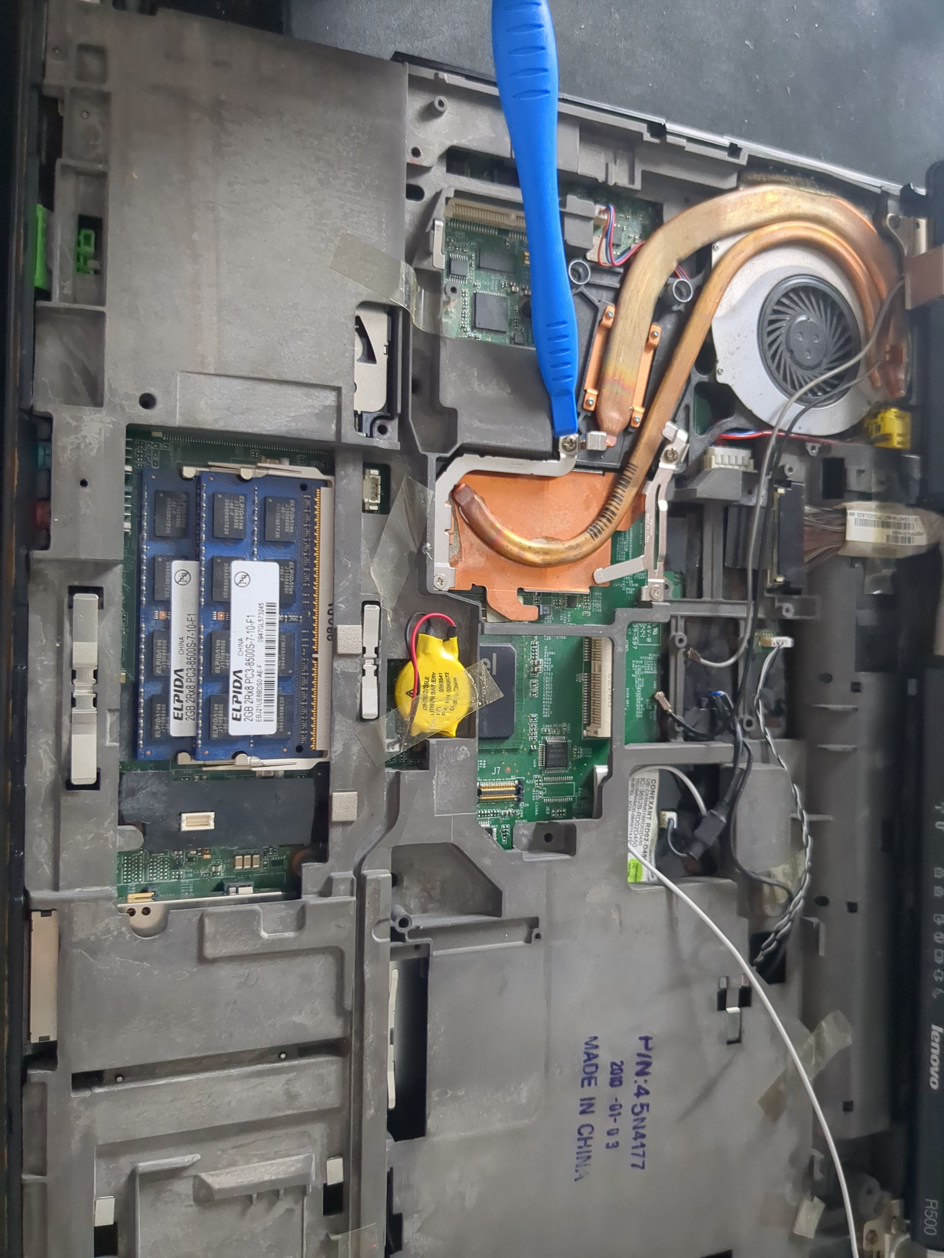
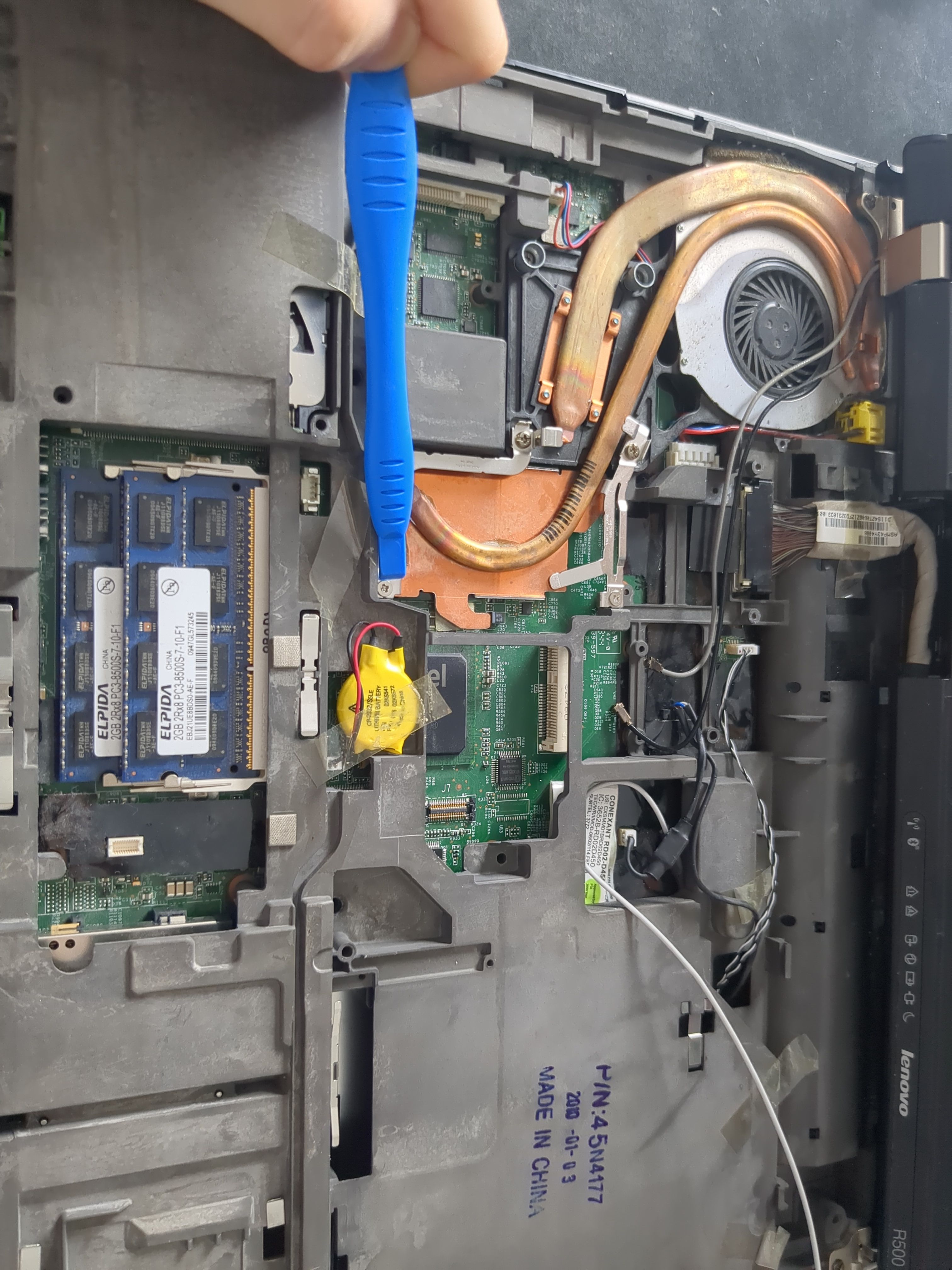
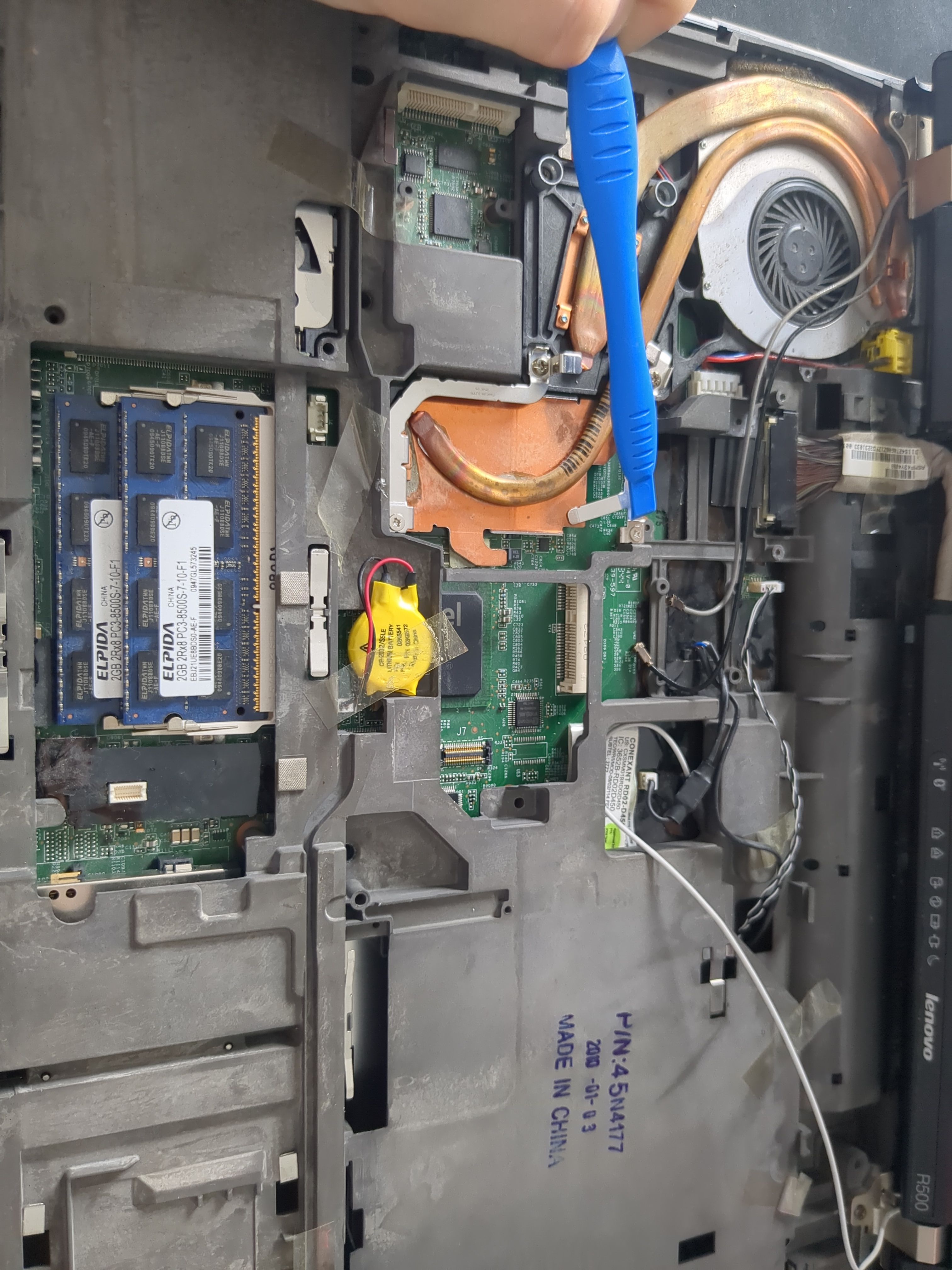
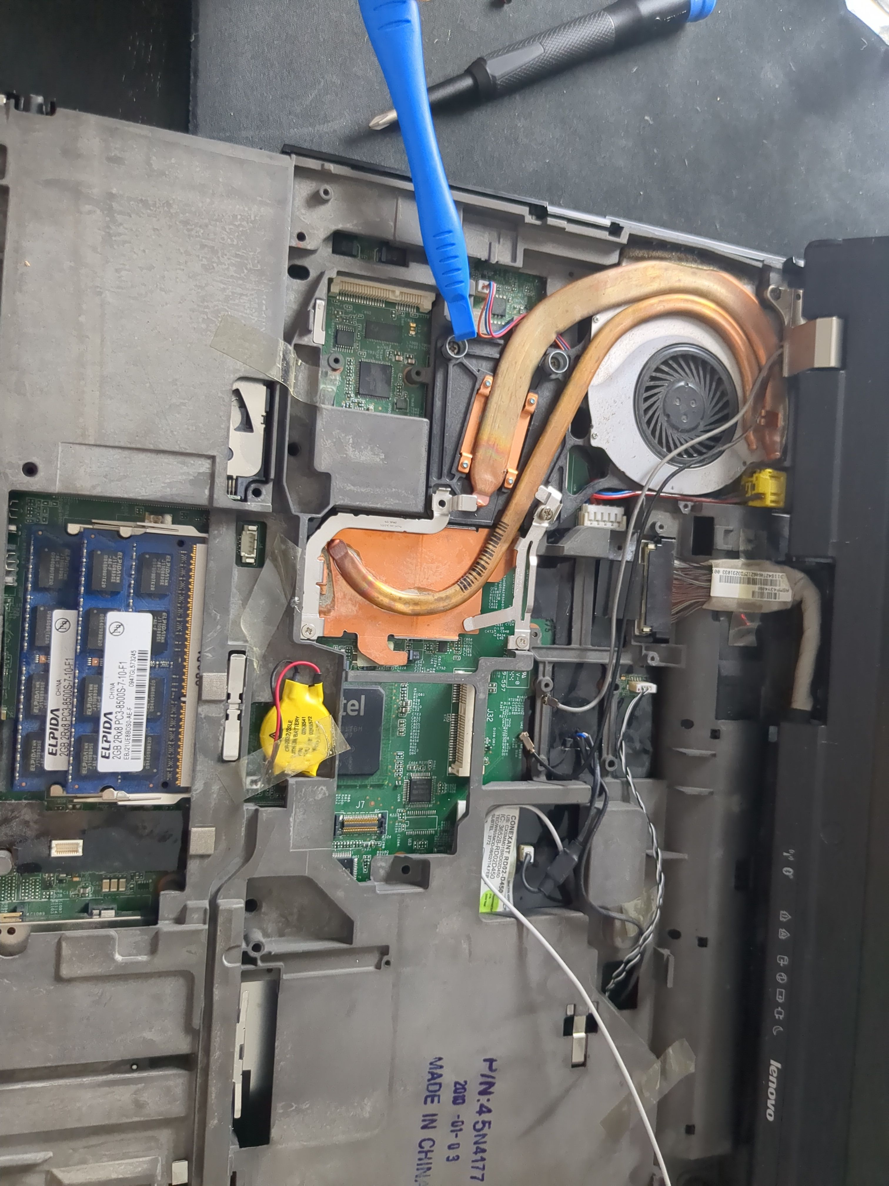
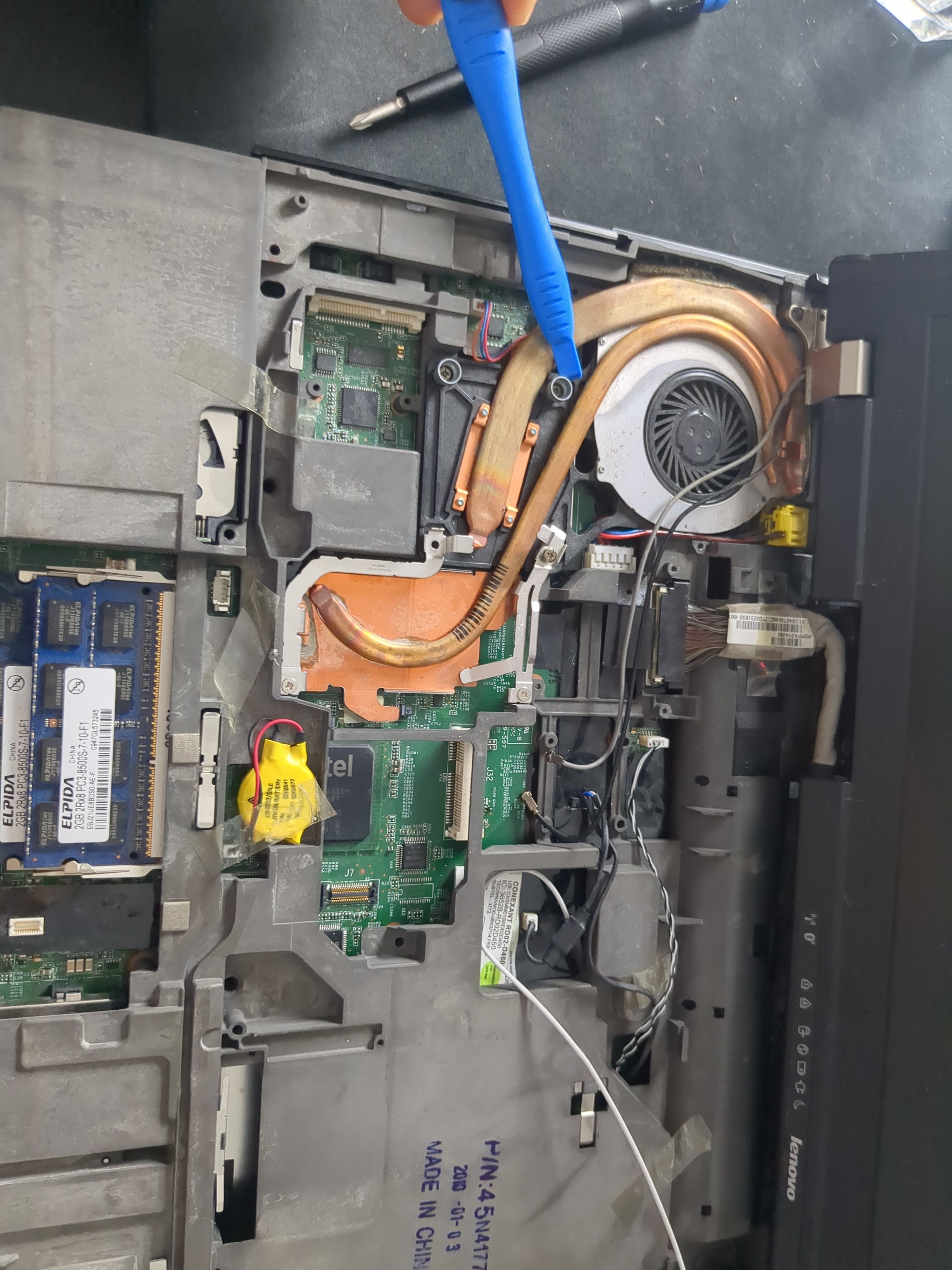
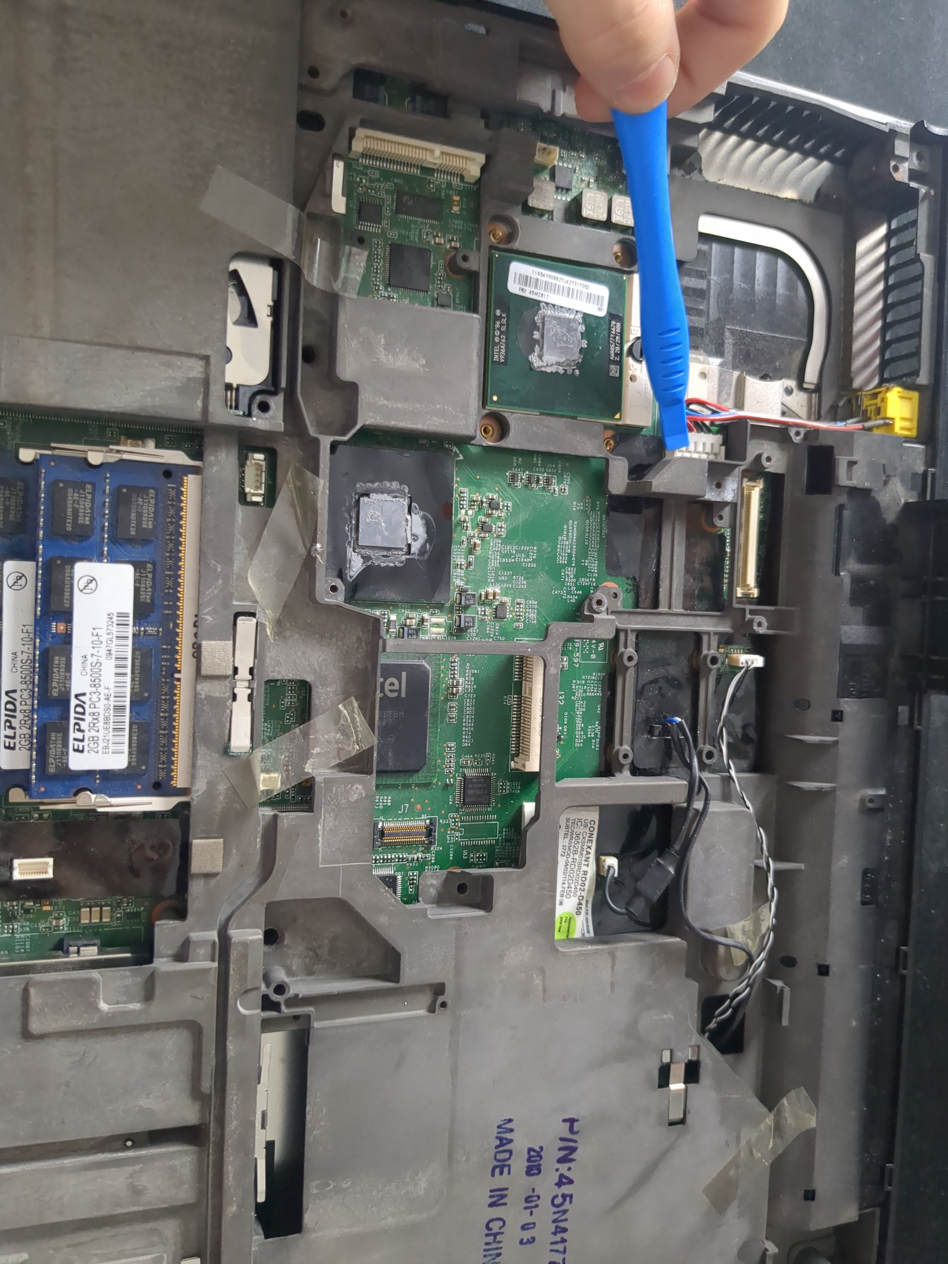
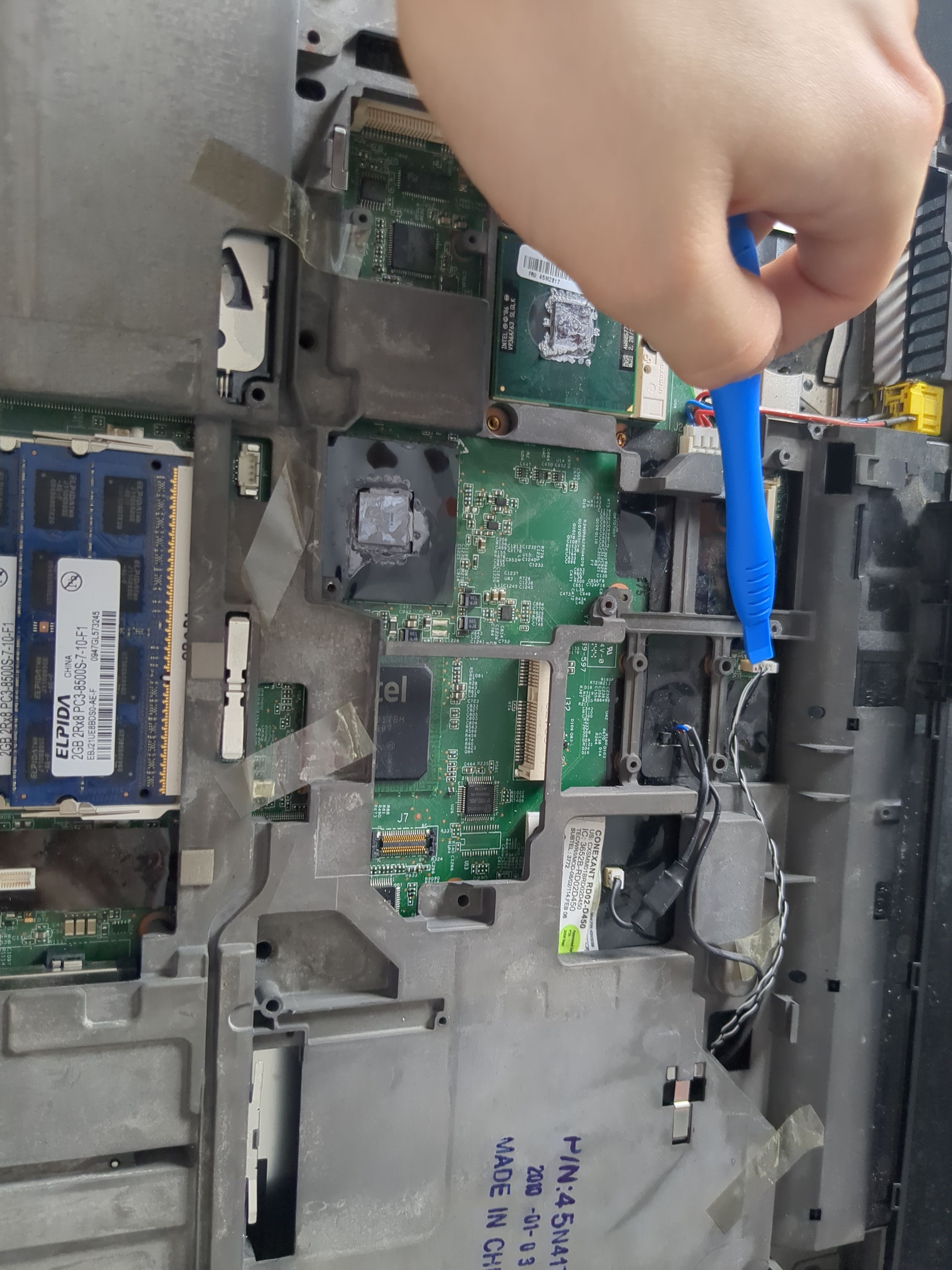
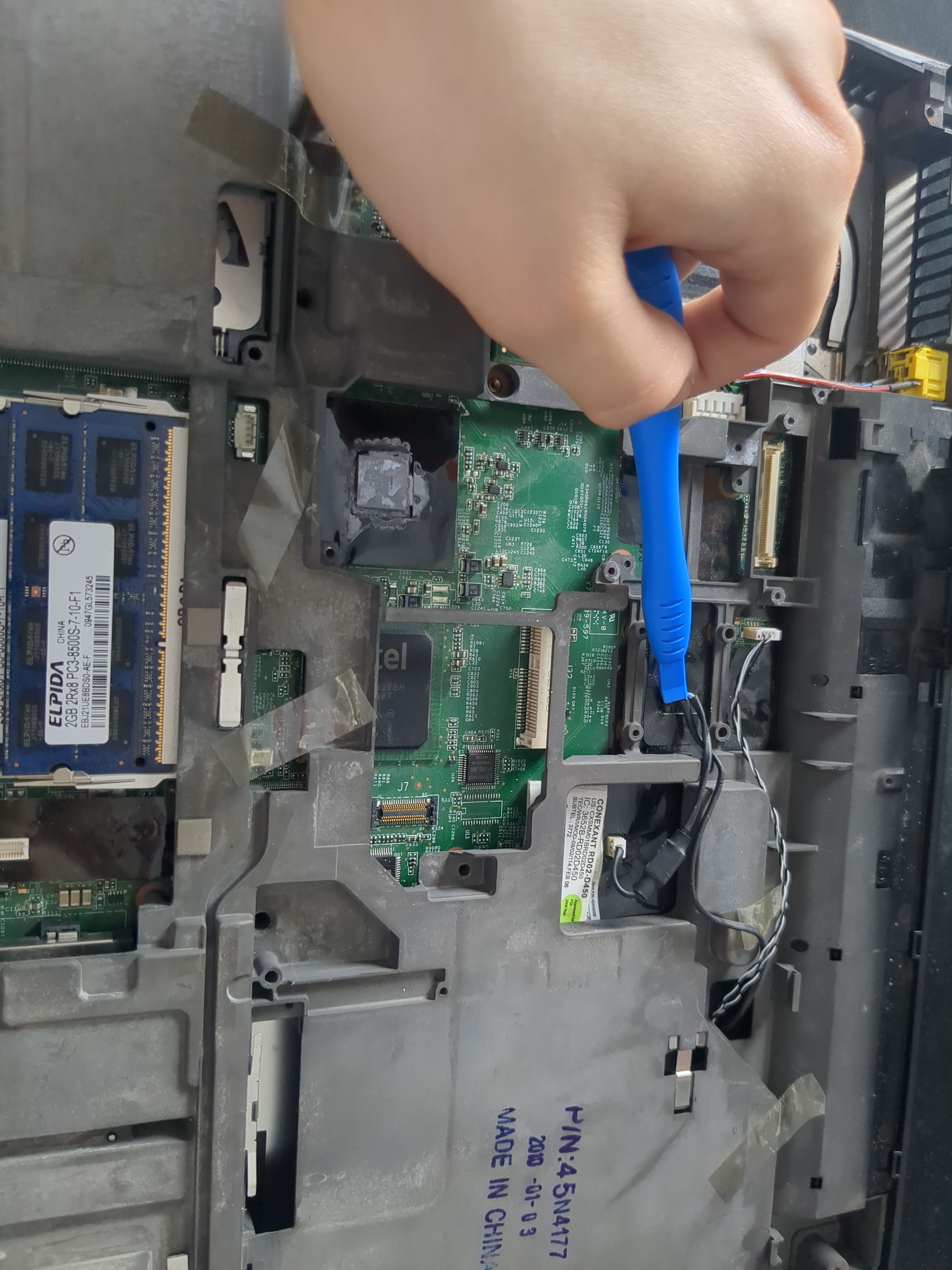
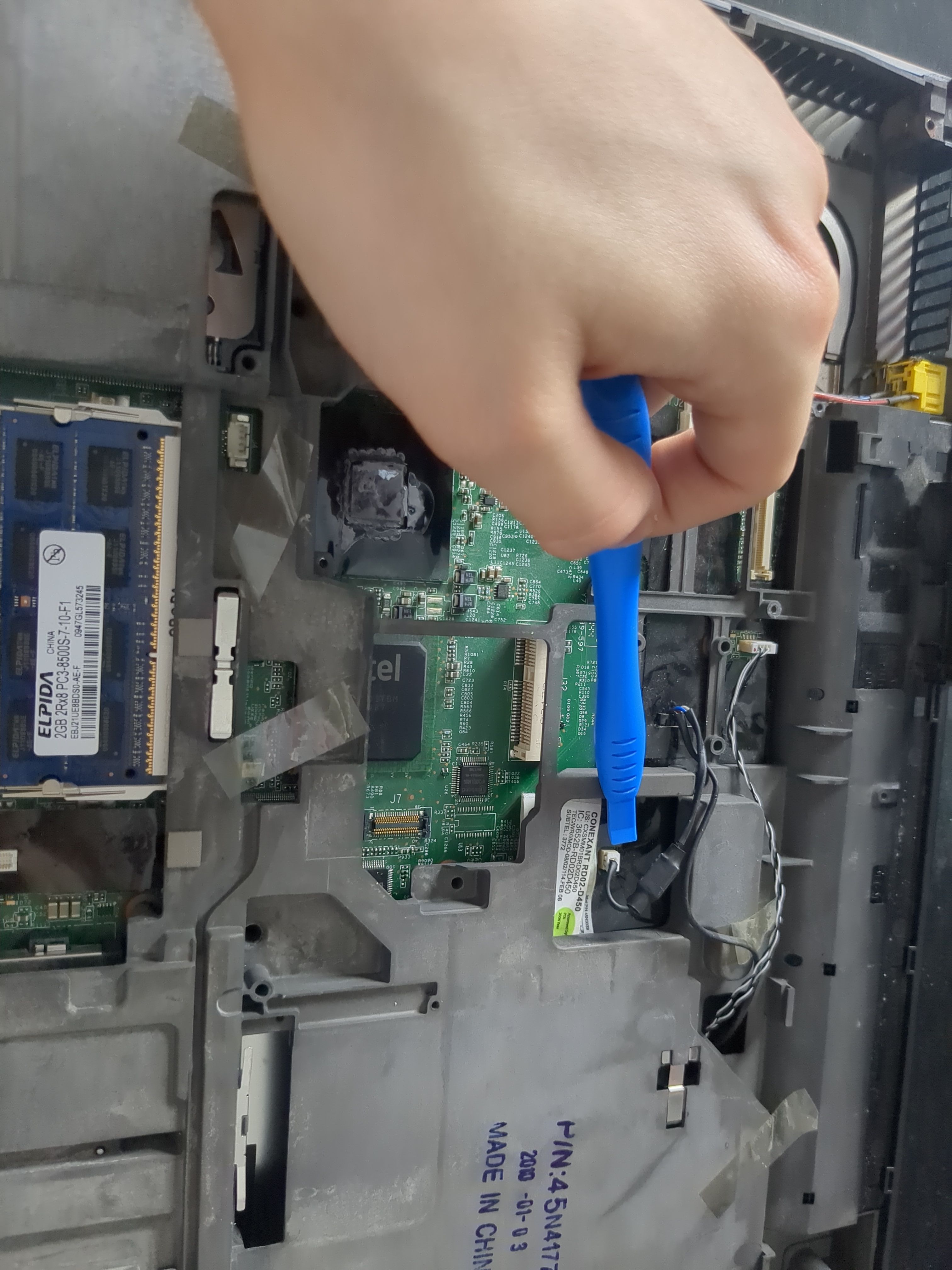
And lastly the fan cable:
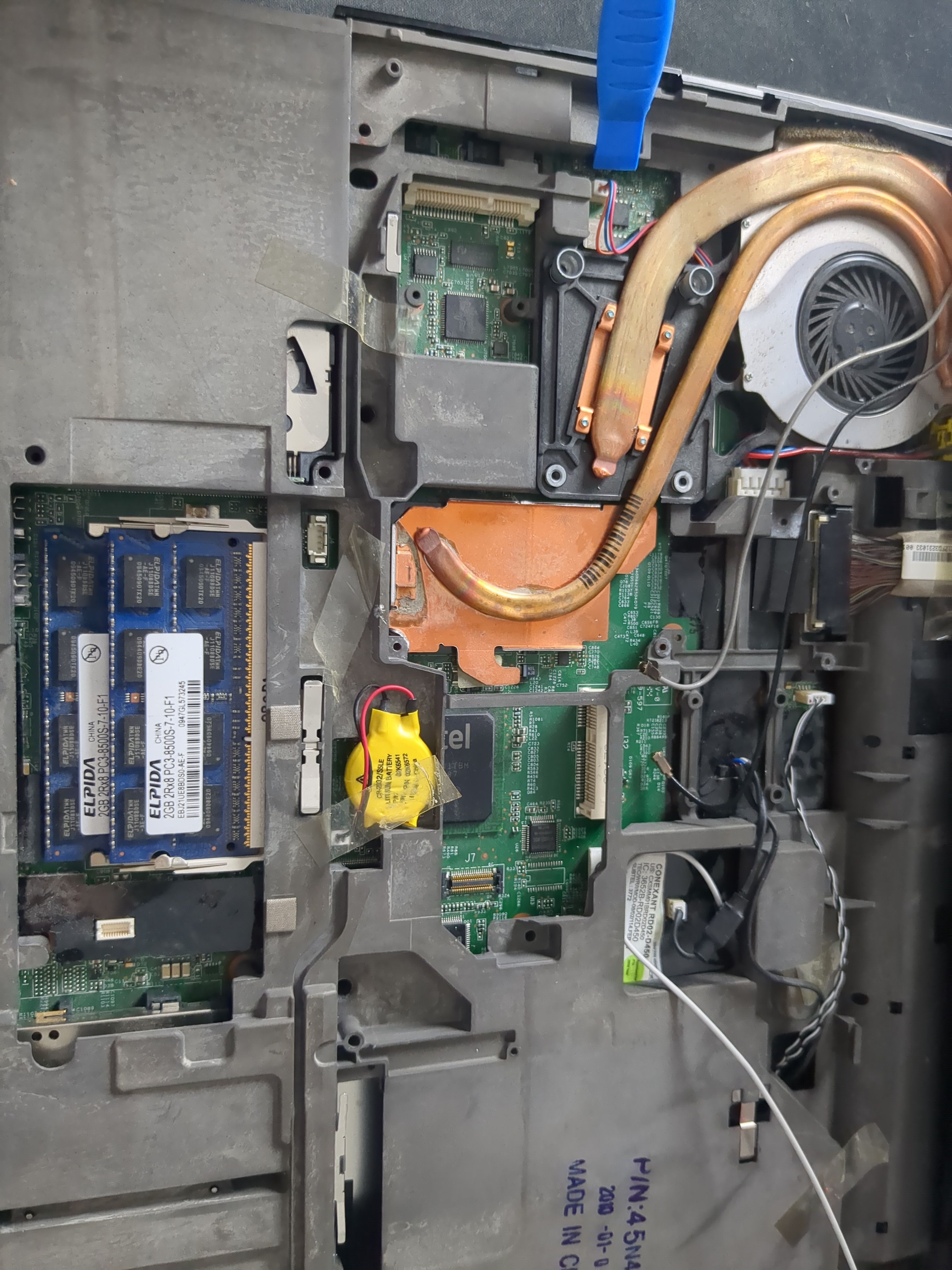
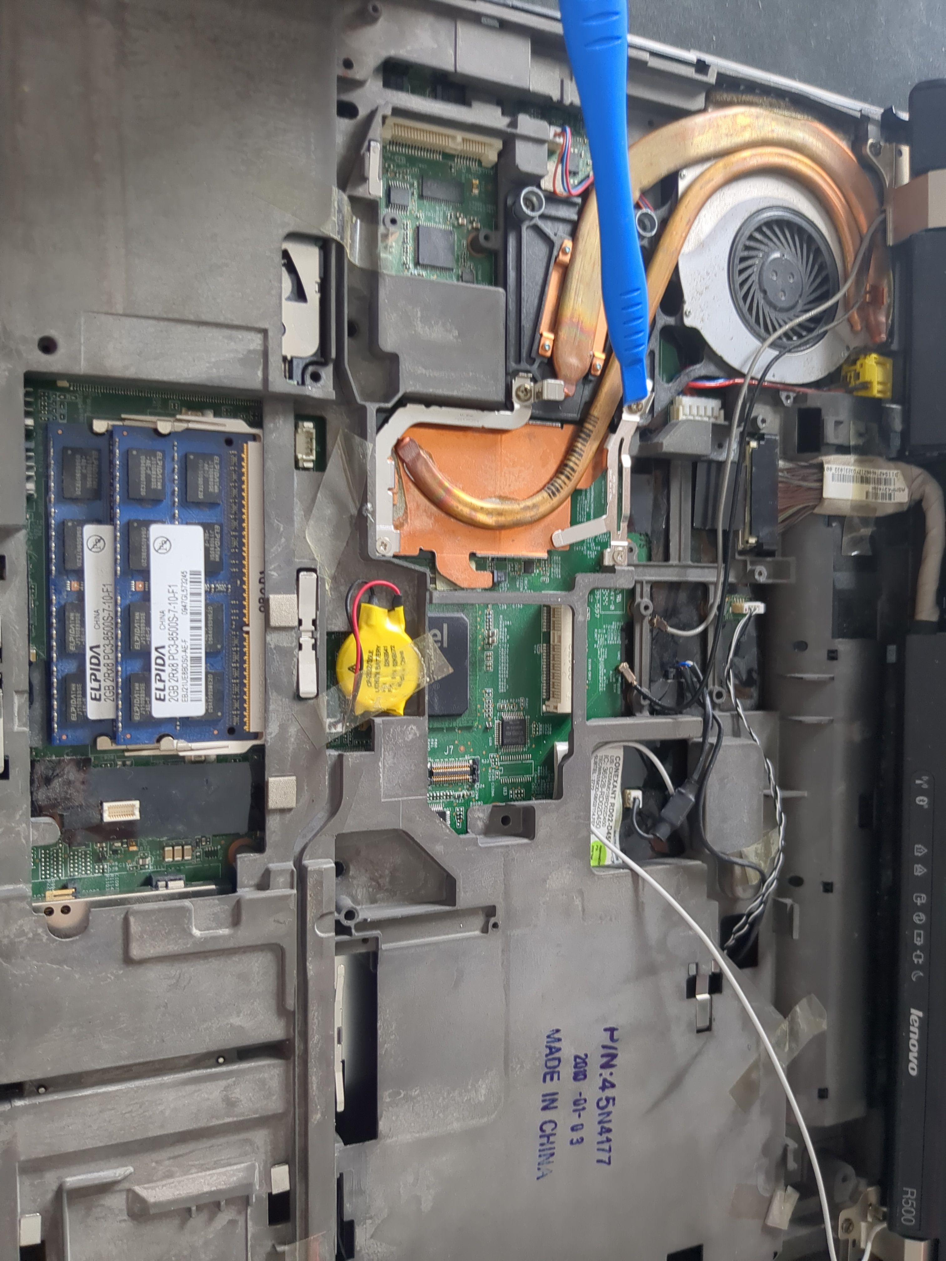
Now remove the cooling system.
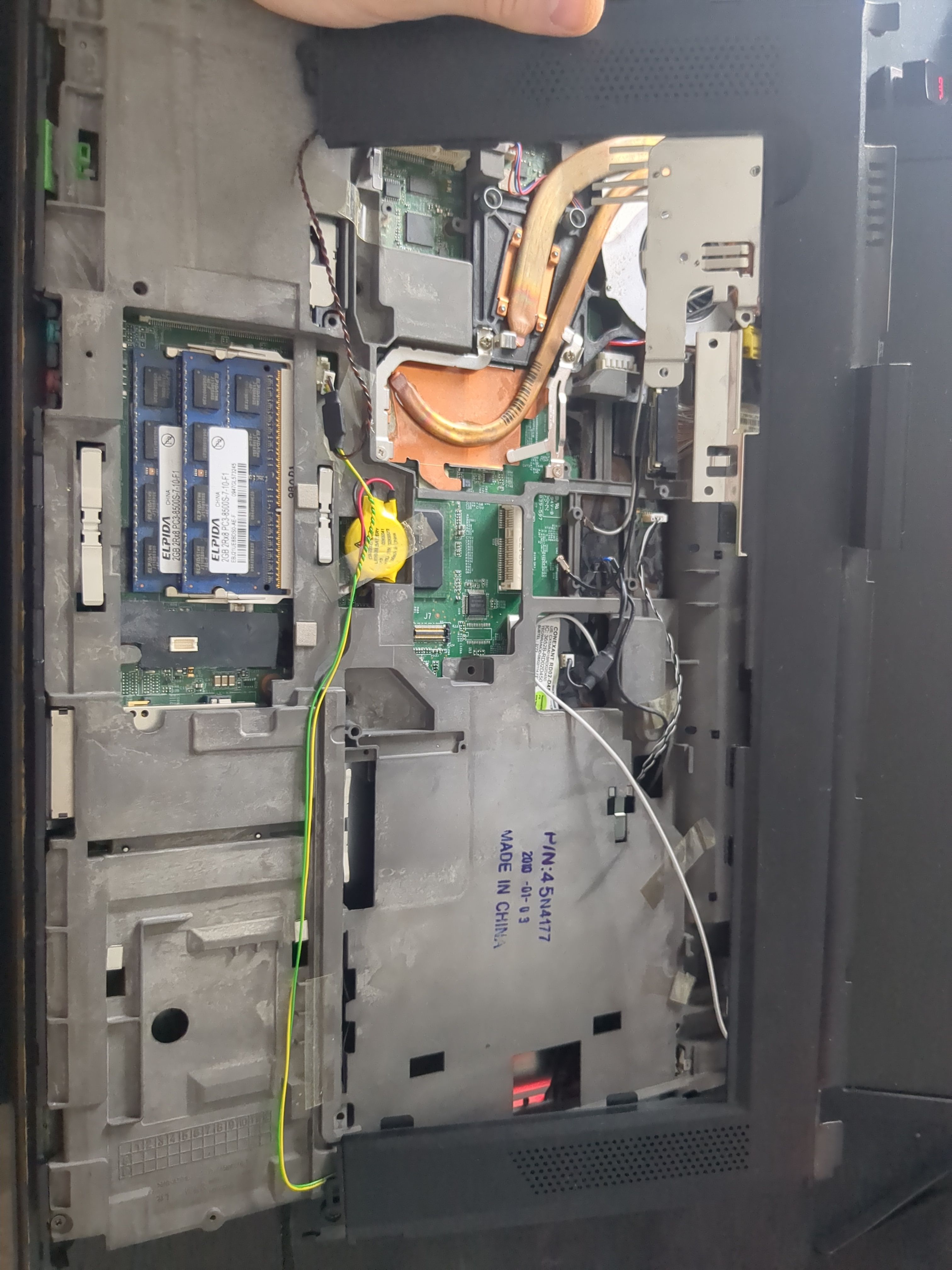
Disconnect all visible cables and the screws shown in the pictures:
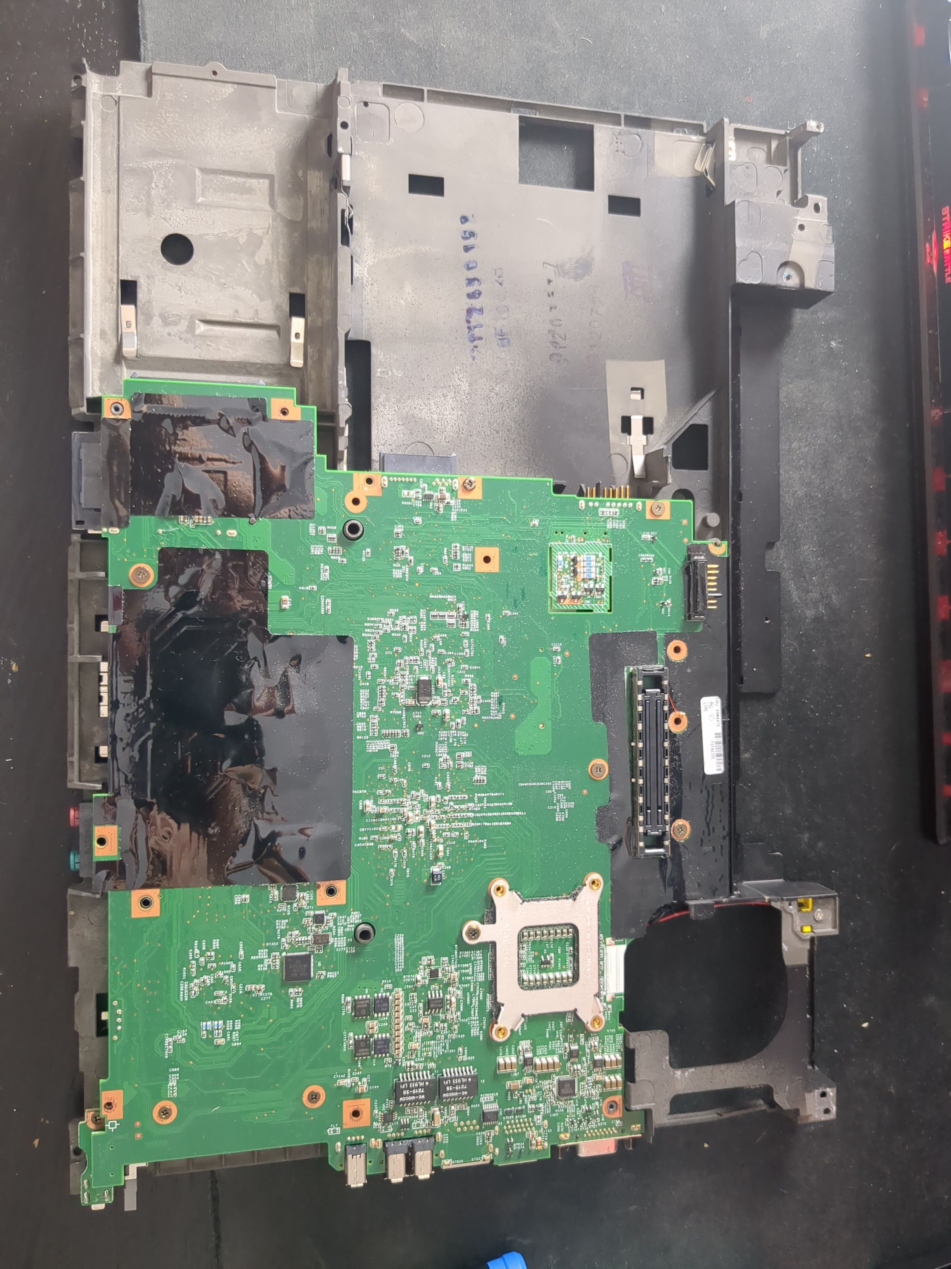
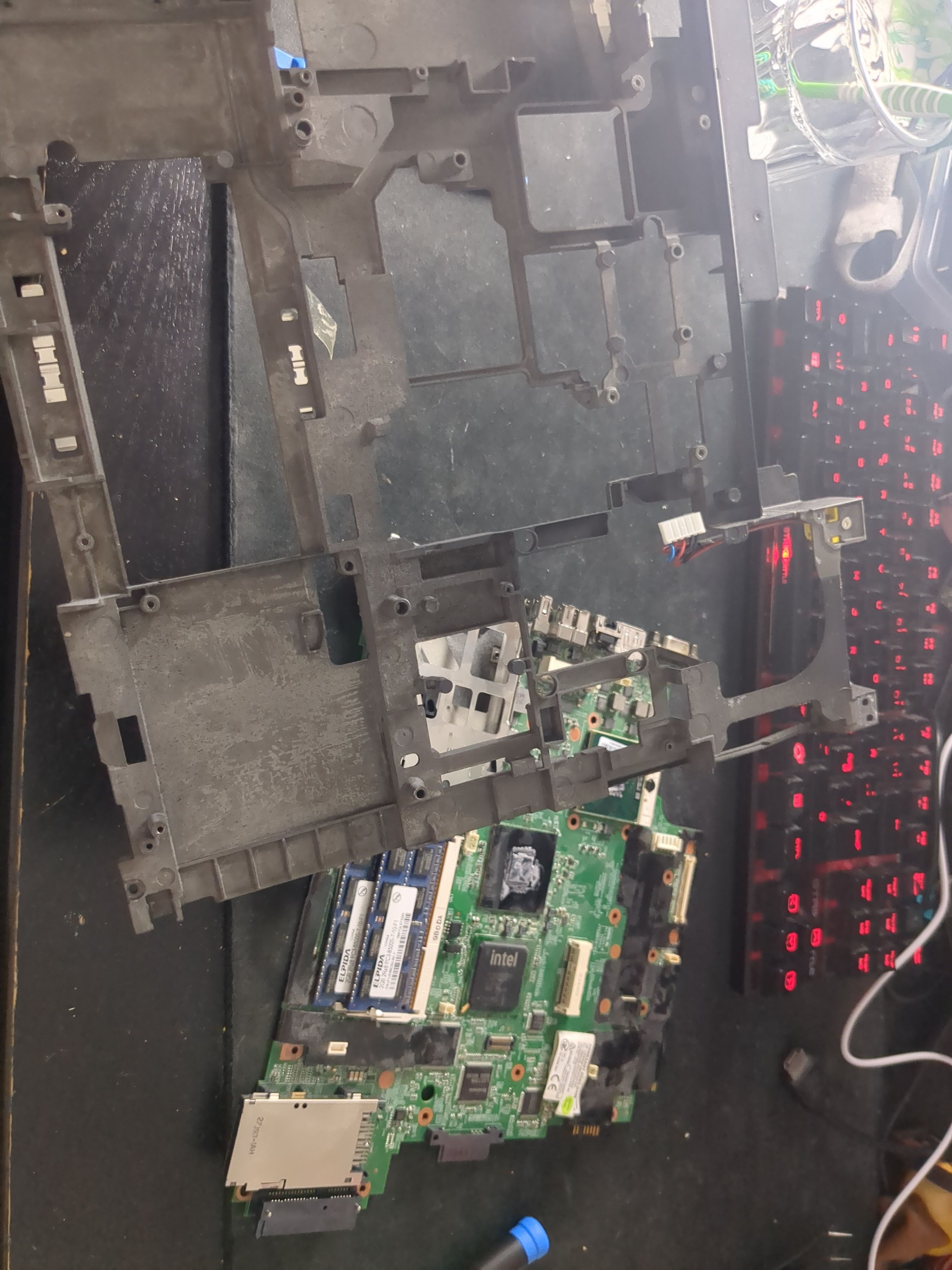
Now remove the motherboard from the outer shell:
Remove all visible screws on the back side of the motherboard:
Now we’re free to remove the inner cage:
Flashing
Before flashing will we wire up the Pi to the clipper, i recommend using the 5250 Pomona Electronics, it’s far superior to the cheap clippers found on Ali Express. The clippers from Ali Express doesn’t connect as securely, and often doesn’t even connect at all. I’ve experienced this at first hand. While writing this blog, i accidentally clipped the connector onto a SOIC8 chip backward. However thanks to the Ali Express clipper’s terrible pin connection, it didn’t even make proper contact. Ironically, its bad quality saved the chip from being fried, save yourself the trouble and buy a proper clipper.
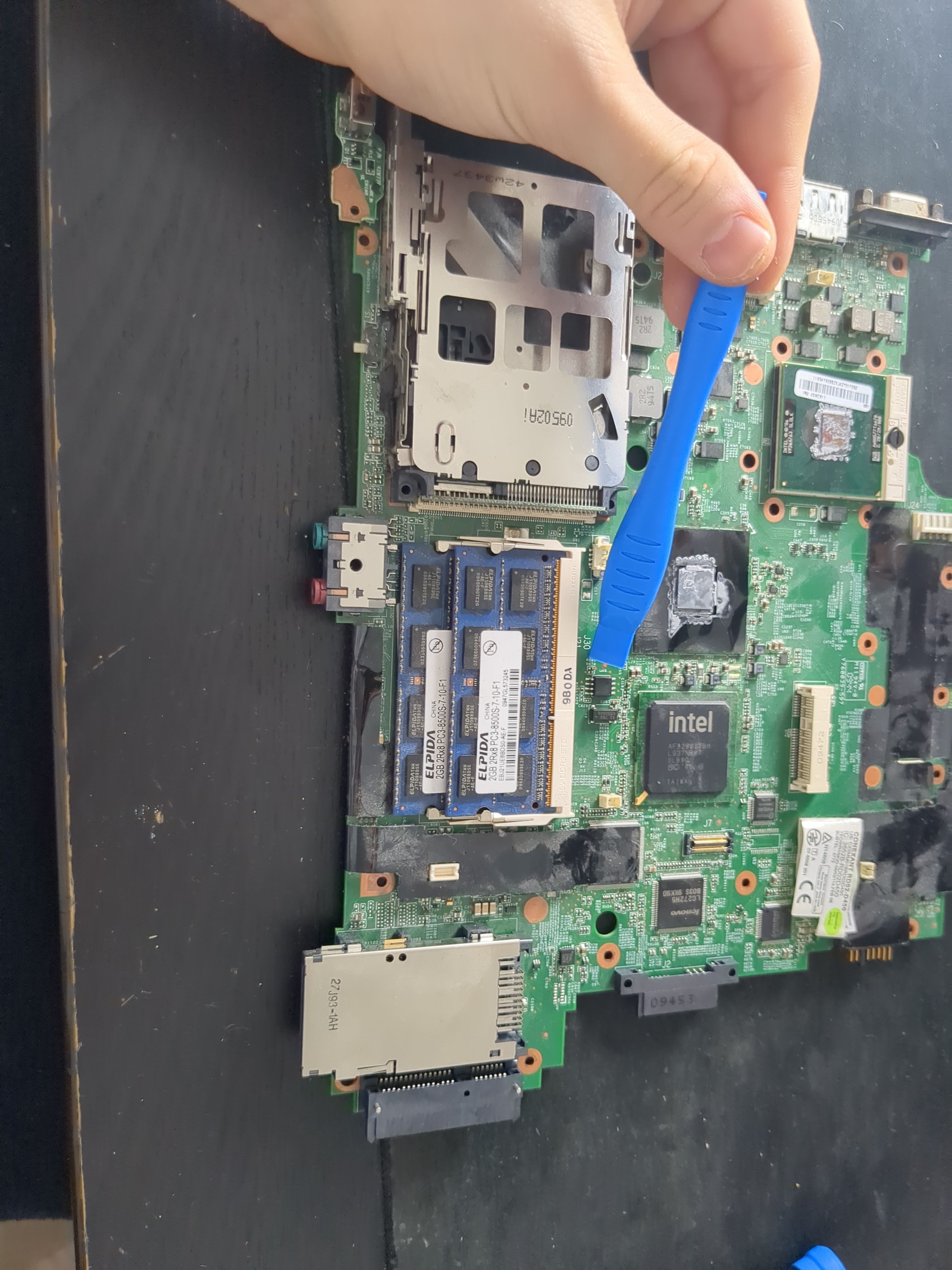
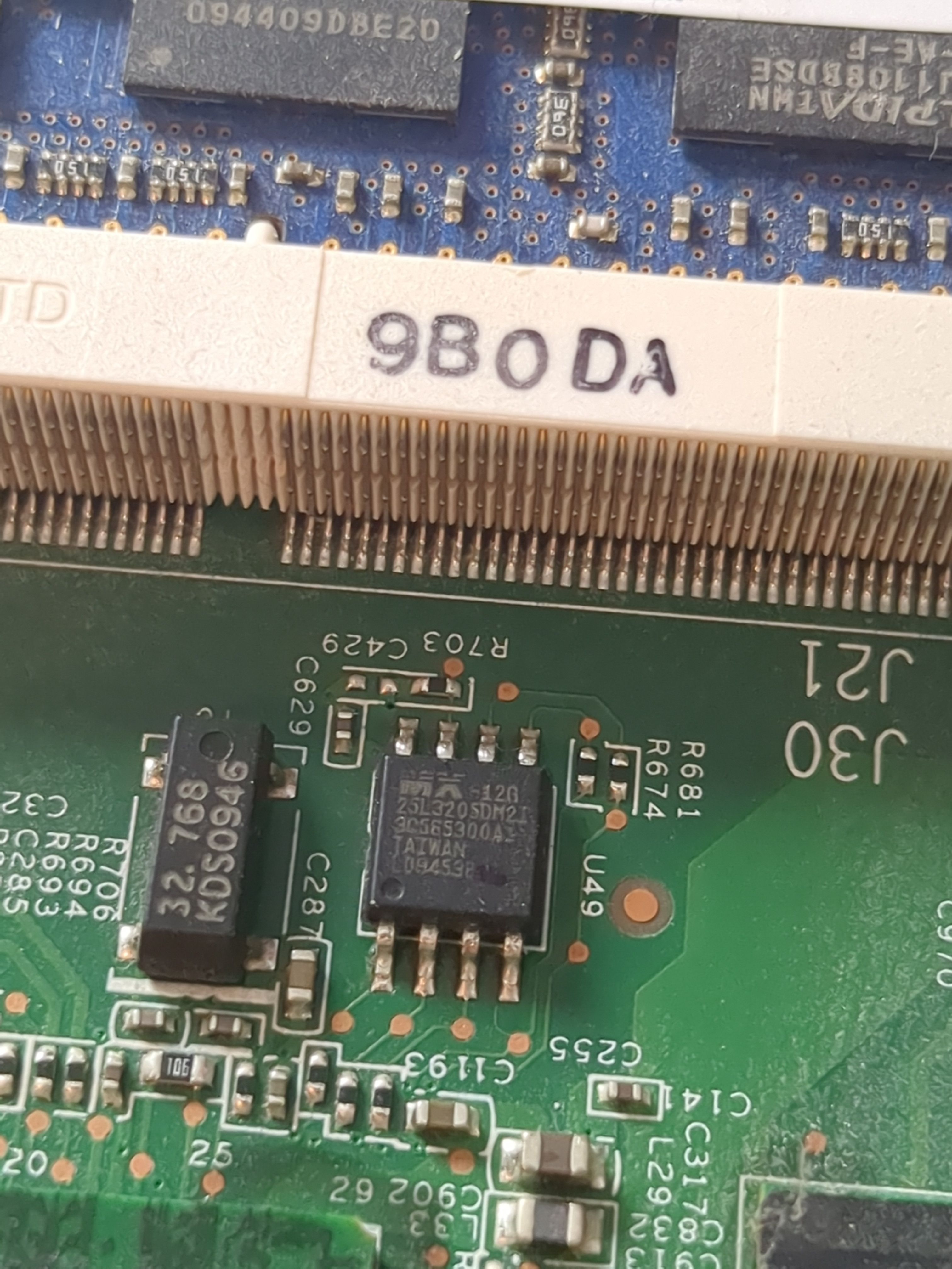
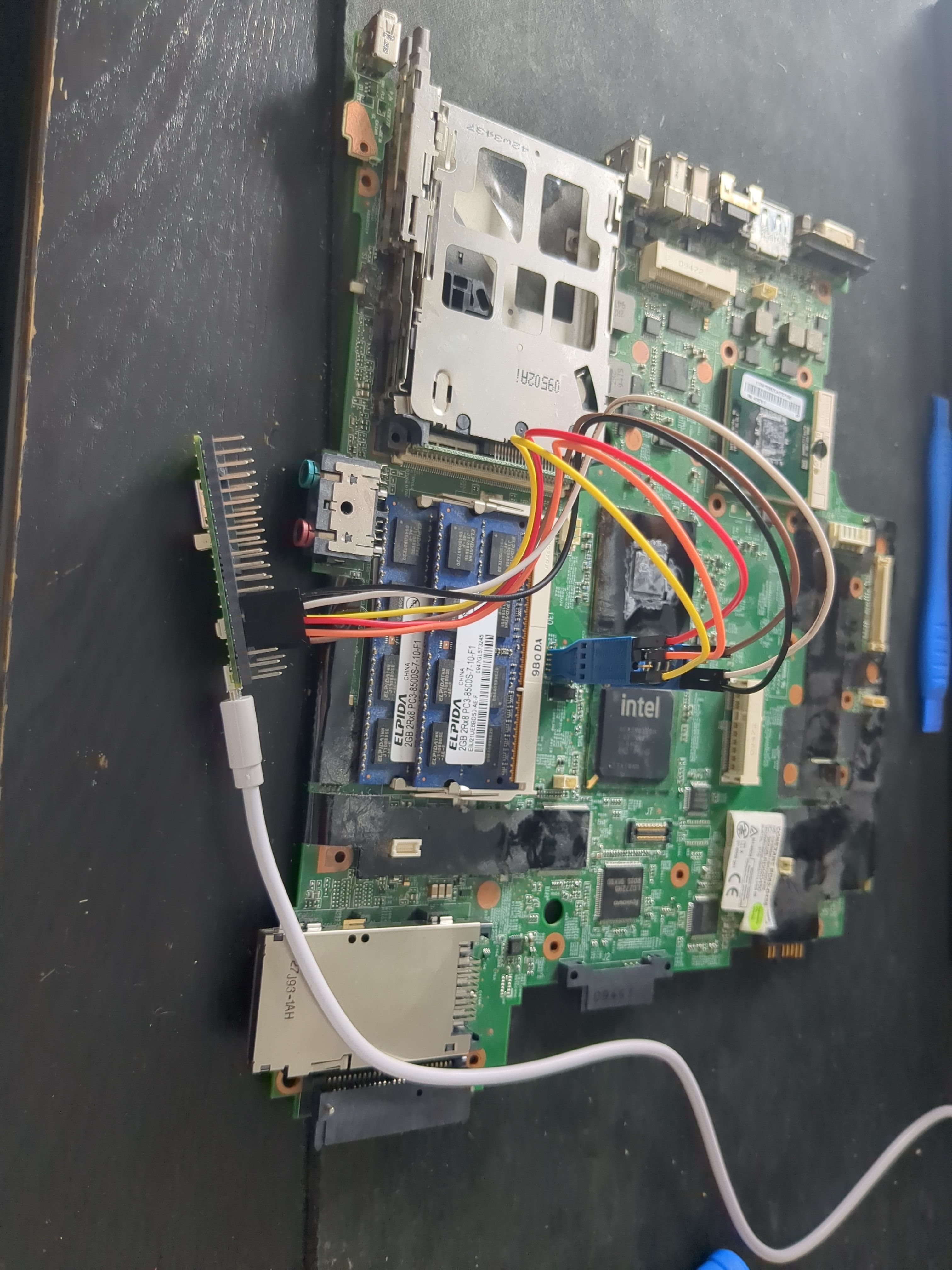
You’ll find the SOIC8 chip next to the ram:
We’ll identify the SOIC8 chip by reading the ID written on it, mine reads MX25L3205D:
Searching this online we find the data sheet, here we see the pin layout.
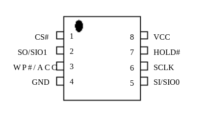
On the data sheet we see a dot in the left top corner. This is also located on the chip itself, use it as a reference point to locate the pins.
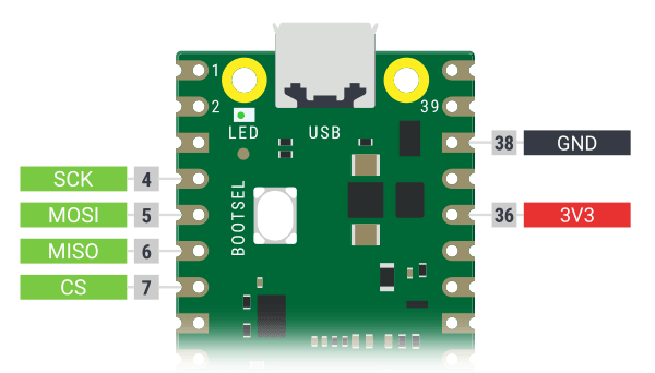
Looking at the data sheet for the pi, we can see what connects where:
| MX25L3205D | Raspberry Pi Pico |
|---|---|
| CS# (Pin 1) | CS (Pin 7) |
| SO (Pin 2) | MISO (Pin 6) |
| GND (Pin 4) | GND (Pin 38) |
| SI (Pin 5) | MOSI (Pin 5) |
| SCLK (Pin 6) | SCK (Pin 4) |
| VCC (Pin 8) | 3.3V (Pin 36) |
Now with the Pi disconnected from the PC, connect the clipper to the chip, aligning the pins (relative to the dot, from the data sheet). Once its firmly in place, connect the Pi to the PC:
Then run the following command:
sudo dmesg | grep "tty"
This will return something similar to this:
[15242.043045] cdc_acm 1-5:1.0: ttyACM0: USB ACM device
Take note of the device ID, in my case: ttyACM0.
Dumping the chip’s firmware can be done with the following command, make sure to replace ttyACMO0 with your device ID, and the chip model as well (-VVV is for maximum verbosity):
sudo flashrom --programmer serprog:dev=/dev/ttyACM0:1152000,spispeed=2000000 --chip MX25L3205D/MX25L3208D -VVV -r read_1.bin
Do it again, this time save to read_2.bin:
sudo flashrom --programmer serprog:dev=/dev/ttyACM0:1152000,spispeed=2000000 --chip MX25L3205D/MX25L3208D -VVV -r read_2.bin
Now compare the files:
cmp -l read_1.bin read_2.bin
This is a way of testing whether or not the connection is stable or not, if these two files are identical you have a great connection, if they’re not identical, you have a loose connection. A loose connection can be cause by long wires, thin wires, dirty pins, etc. Repeat this until you have two identical reads, this will be your backup.
Now we can finally write, again make sure to replace ttyACMO0 with your device ID, as well as the chip and the rom file downloaded from here at /20250107/roms/canoeboot-20250107_r500_4mb.tar.xz, make sure to select a coreboot version, not txtmode, as well as choosing the correct keyboard layout:
sudo flashrom --programmer serprog:dev=/dev/ttyACM0:1152000,spispeed=2000000 --chip MX25L3205D/MX25L3208D -VVV -w "seagrub_r500_4mb_libgfxinit_corebootfb_usqwerty.rom"
After successfully writing it’s good practice to check if we’ve written correctly. This can be done by dumping again and comparing the dump to the canoeboot rom file, if they’re not identical, you’ll need to reflash the chip.
Assembling
Assembling the PC, can be done by following the dissemble guide backwards. Remember to reapply new thermal paste, as well a the new WiFi card, personally I’m using the Atheros AR5B95, while its compatible with open source drivers.
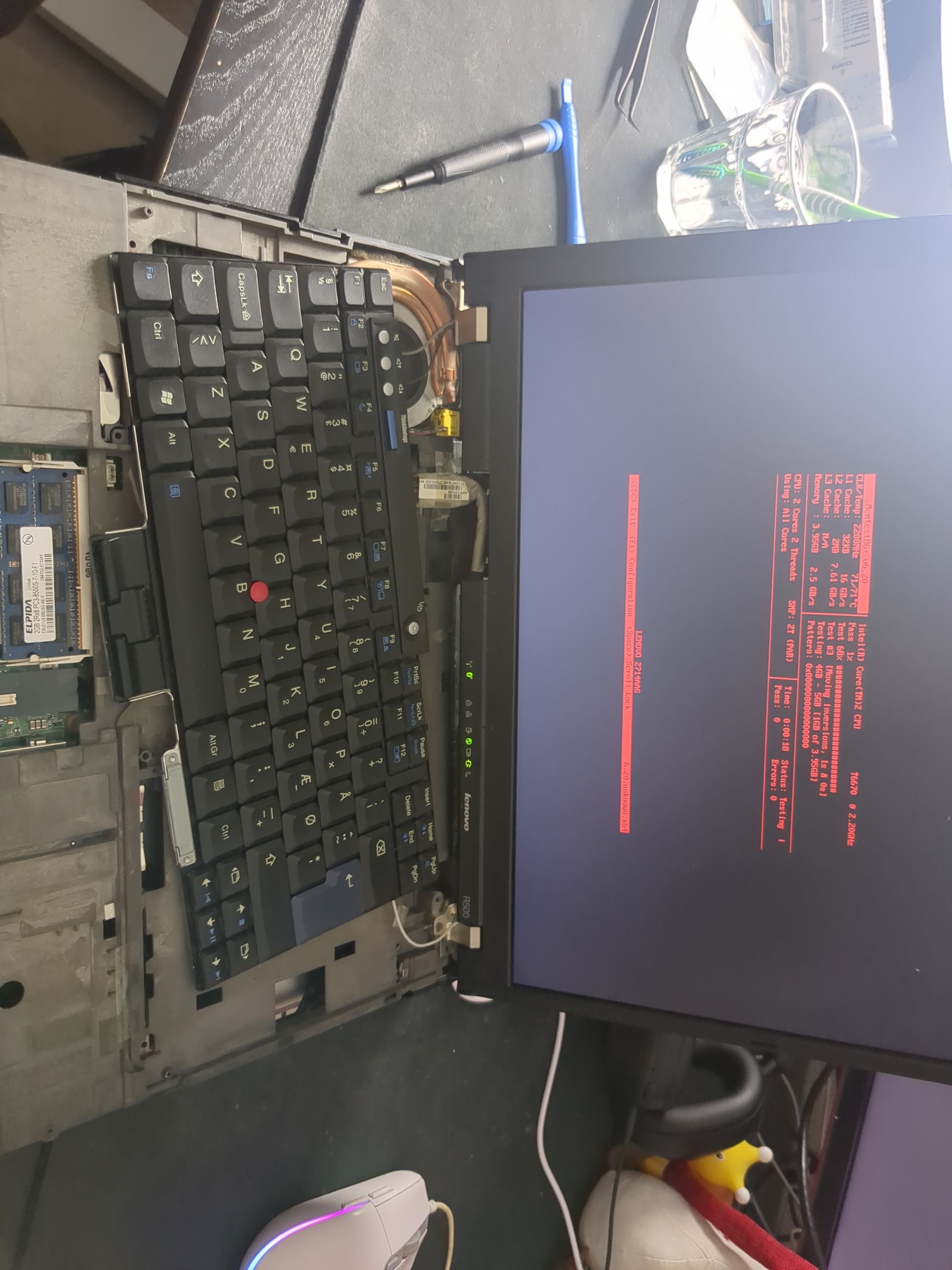
Testing
Perform a memory test after booting up the pc for the first time, this is an additional way of making sure the PC is working correctly. The memory test can be located inside the BIOS:
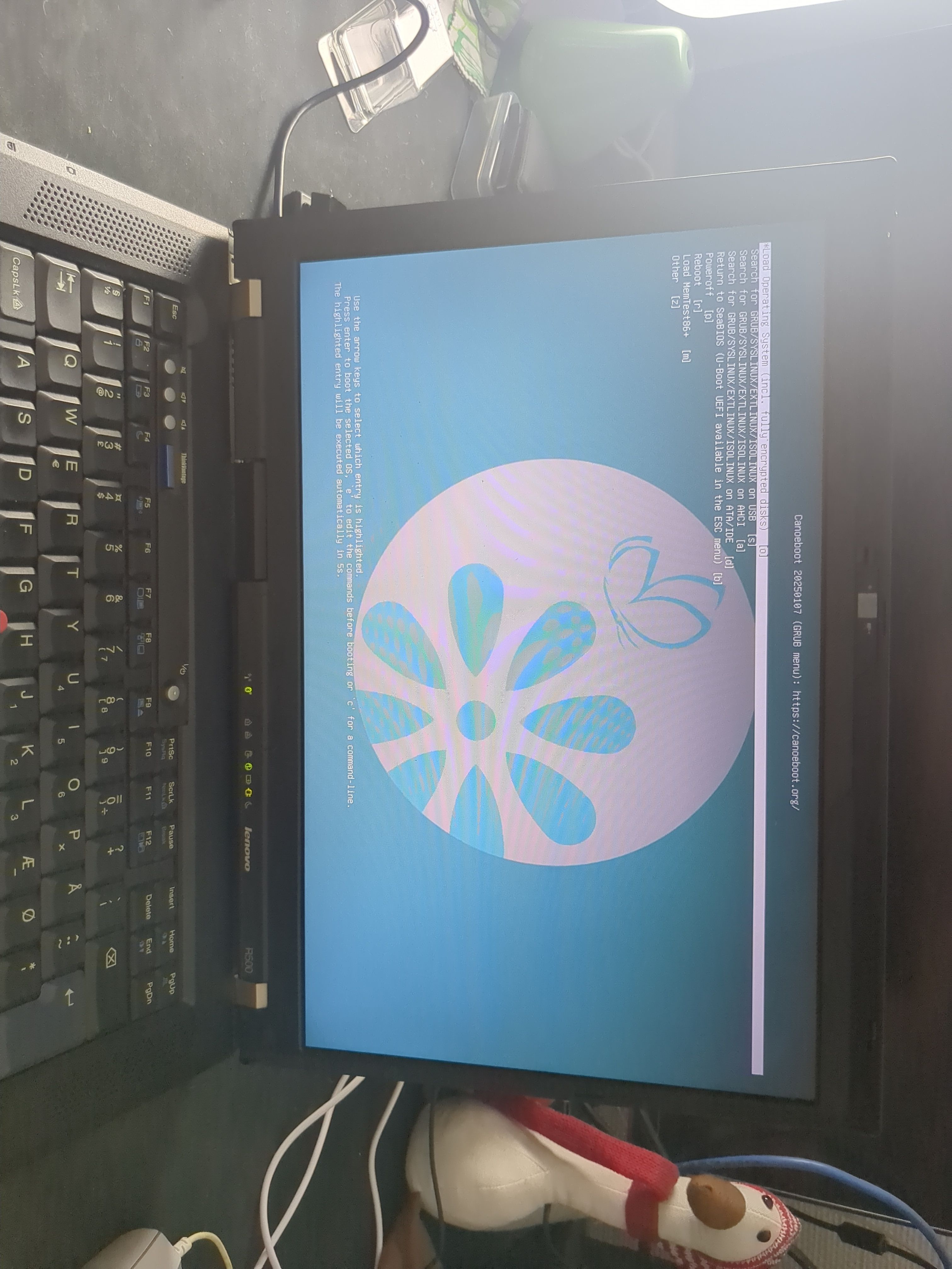
Now we’re running Canoeboot:
Installing OS
I’m going with trisquel mini, why is explained here. If you run into any issue while installing, checking the wiki might be a good idea.